


In the complex world of software development, planning is often the difference between a stable application and a fragile system. Before writing a single line of executable code, architects and developers rely on visual blueprints to map out the structure of their software. One of the most critical tools in this process is the object-oriented class diagram. These diagrams provide a static view of the system, detailing classes, their attributes, methods, and the intricate relationships that bind them together.
Whether you are an aspiring system analyst or a seasoned developer refining your skills, understanding how to construct these diagrams is fundamental. This guide walks you through the process of designing your first object-oriented class diagram using standard modeling practices. We will explore the core elements, the semantics of relationships, and the step-by-step workflow required to create a robust design.
Understanding the Building Blocks of a Class Diagram 🧱
Before drawing lines and boxes, you must understand what each shape represents. A class diagram is not merely a drawing; it is a specification of the system’s data and behavior. The primary element is the class.
The Class Structure
Visually, a class is represented by a rectangle divided into three compartments. This structure allows you to organize information logically:
- Top Compartment: Contains the name of the class. This should be a noun, such as Customer, Invoice, or Product.
- Middle Compartment: Lists the attributes (properties) of the class. These describe the state or data held by the object.
- Bottom Compartment: Lists the methods (operations). These describe the actions the object can perform.
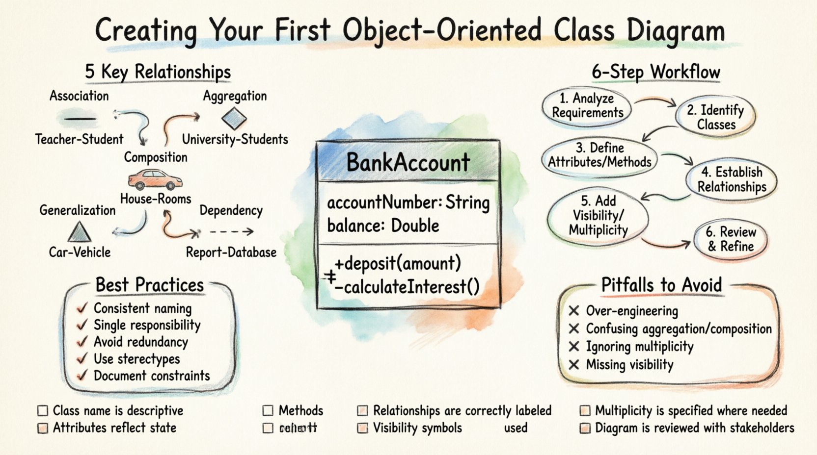
Consider a simple BankAccount class. Its attributes might include accountNumber and balance. Its methods might include deposit() and withdraw(). This separation ensures clarity between what an object is (data) and what an object does (behavior).
Attributes and Data Types
Attributes define the specific data points associated with a class. When documenting these, it is important to specify the data type. For example, an integer for a count, a string for a name, or a boolean for a status flag. In a formal diagram, you might see the attribute name followed by a colon and the type, such as age: Integer.
Additionally, you must consider the scope of these attributes. Are they specific to a single instance, or do they belong to the class itself? While static attributes exist, for a beginner’s diagram, focusing on instance attributes is the standard starting point.
Methods and Operations
Methods are the functions that manipulate the attributes of a class. They represent the logic of the system. When defining methods, list the name of the operation followed by parameters in parentheses. For example, calculateInterest(rate).
Just like attributes, methods have visibility levels. This controls who can access or modify them from outside the class. The three standard visibility markers are:
- Public (+): Accessible by any other class.
- Private (-): Accessible only within the class itself.
- Protected (#): Accessible within the class and its subclasses.
Mapping Relationships: The Connections That Matter 🔗
A class diagram is rarely just a collection of isolated boxes. The true power of object-oriented design lies in how these classes interact. Relationships define the links between classes. Misinterpreting these links can lead to tight coupling and difficult maintenance later on.
1. Association
An association represents a structural relationship where one class is connected to another. It implies that objects of one class have references to objects of another class. A simple line connects the two classes. You can label this line to describe the nature of the link, such as “employs” or “owns”.
Cardinality is often defined on associations to show how many objects are involved. For example, a Department might have a 1-to-many association with Employee, meaning one department employs many employees.
2. Aggregation
Aggregation is a specific type of association that represents a whole-part relationship. It implies a has-a relationship where the part can exist independently of the whole. If the whole is destroyed, the parts continue to exist.
Imagine a University and its Students. If the university closes, the students still exist as individuals. This is represented by a hollow diamond on the whole side of the line.
3. Composition
Composition is a stronger form of aggregation. It also represents a whole-part relationship, but with a lifecycle dependency. The parts cannot exist without the whole. If the whole is destroyed, the parts are destroyed with it.
Consider a House and its Rooms. If the house is demolished, the rooms cease to exist in that context. This is represented by a filled diamond on the whole side of the line.
4. Generalization (Inheritance)
Generalization is the mechanism of inheritance. It allows a subclass to inherit attributes and methods from a superclass. This promotes code reuse and establishes an is-a relationship. For example, a Car is a Vehicle.
Visually, this is drawn as a solid line with a hollow triangle arrowhead pointing toward the superclass (the parent).
5. Dependency
Dependency represents a usage relationship. One class depends on another to perform an operation, but the dependency is often temporary. For instance, a ReportGenerator class might depend on a DatabaseConnection class only during the time it is generating a report.
This is drawn as a dashed line with an open arrowhead pointing from the dependent class to the used class.
Comparison of Common Relationships
| Relationship Type | Symbol | Meaning | Example |
|---|---|---|---|
| Association | Solid Line | Structural link between objects | Teacher teaches Student |
| Aggregation | Hollow Diamond | Whole-Part (Independent) | Team has Members |
| Composition | Filled Diamond | Whole-Part (Dependent) | Order has LineItems |
| Generalization | Hollow Triangle | Inheritance (Is-A) | Invoice is Document |
| Dependency | Dashed Line | Usage Relationship | PrintService uses Printer |
Step-by-Step Guide to Designing Your Diagram 🛠️
Now that you understand the vocabulary and symbols, let us walk through the actual process of creating a diagram from scratch. This workflow is designed to ensure logical consistency and clarity.
Step 1: Analyze the Requirements
Start by reading the functional requirements or use case descriptions. Identify the nouns and verbs. Nouns often become classes, while verbs often become methods or associations. For instance, if a requirement states “The system must process a payment,” the nouns might be System, Payment, and Transaction.
Step 2: Identify the Core Classes
List the classes you have identified. Do not worry about perfection yet. Just ensure you have the main entities. In an e-commerce scenario, you might list User, Product, Order, and Payment.
Step 3: Define Attributes and Methods
For each class, brainstorm the data it needs to store and the actions it needs to perform. Be specific. Instead of just listing data, list customerName or orderDate. For methods, focus on the public interface that other classes will interact with.
Step 4: Establish Relationships
Draw lines between the classes to represent how they interact. Ask yourself: Can one object exist without the other? Is one a type of the other? Use the relationship symbols defined earlier to denote the nature of the link accurately. Mislabeling a composition as an aggregation is a common error that can lead to memory management issues in the final code.
Step 5: Assign Visibility and Multiplicity
Add the +, –, or # symbols to your attributes and methods. Determine the multiplicity on your relationship lines. Does one user have one address, or many? Does a product have zero or more reviews? Use notation like 1..* (one to many) or 0..1 (zero or one).
Step 6: Review and Refine
Once the diagram is complete, step back and review it. Does it make sense? Are there circular dependencies? Is the diagram too complex? Simplify where possible. A diagram should communicate ideas, not confuse them.
Best Practices for Clean and Effective Diagrams 🎯
Creating a diagram is easy; creating a good diagram requires discipline. Follow these guidelines to ensure your work remains maintainable and understandable by your team.
- Keep Names Consistent: Use standard naming conventions. Avoid abbreviations unless they are universally understood within your team. Use CamelCase for class names (e.g., CustomerOrder) and camelCase or snake_case for attributes depending on your language standards.
- Limit Class Size: If a class has too many attributes or methods, it may be a sign of poor cohesion. Consider splitting it into smaller, more focused classes. A class should ideally have a single responsibility.
- Avoid Redundancy: Do not repeat attributes across classes unless necessary for inheritance. If two classes share common data, consider extracting that data into a parent class.
- Use Stereotypes for Clarity: If your modeling tool supports it, use stereotypes to indicate specific roles, such as <
>, < >, or < >. This adds semantic value to the diagram. - Document Constraints: If there are business rules that cannot be captured in the structure, use notes or comments to attach them to the relevant class or relationship.
Common Pitfalls to Avoid ⚠️
Even experienced designers can fall into traps. Being aware of these common mistakes will save you time during the coding phase.
- Over-Engineering: Do not try to model every single possible relationship. Focus on the requirements you have now, not hypothetical future ones. This leads to a diagram that is difficult to change later.
- Confusing Aggregation and Composition: This is the most frequent error. Remember: Composition implies ownership and lifecycle dependency. If the part survives the whole, it is aggregation.
- Ignoring Multiplicity: Leaving multiplicity blank forces developers to guess. Always specify 0..1, 1, or 1..*.
- Ignoring Visibility: Making everything public defeats the purpose of encapsulation. Keep internal data private and expose only what is necessary.
- Missing Relationships: It is common to forget bidirectional associations. If Class A knows about Class B, does Class B know about Class A? Ensure the link is modeled correctly in both directions if needed.
Validating Your Design 🧐
Before finalizing your diagram, run a mental validation check. Does the design support the core use cases? If a user needs to “Place an Order,” can the classes support that flow? Trace the path through the diagram.
Check for circular dependencies. If Class A depends on Class B, and Class B depends on Class A, this can cause initialization issues. While not always fatal, it is a warning sign that the design might need refactoring.
Validation Checklist
- ☐ Are all class names nouns and capitalized?
- ☐ Are all attributes and methods clearly visible?
- ☐ Are relationships labeled with correct cardinality?
- ☐ Are visibility markers (+, -, #) applied consistently?
- ☐ Is there a clear distinction between inheritance and usage?
- ☐ Does the diagram match the business requirements?
- ☐ Is the diagram readable without excessive zooming or panning?
Conclusion and Next Steps 🚀
Designing an object-oriented class diagram is a foundational skill for any software professional. It bridges the gap between abstract requirements and concrete code. By following the steps outlined in this guide, you can create diagrams that serve as reliable blueprints for development.
Remember that diagrams are living documents. As requirements evolve, your diagrams should evolve with them. Do not treat them as static artifacts to be drawn once and forgotten. Regular updates ensure that the visual documentation remains a true reflection of the system.
Practice is the key to proficiency. Start with small systems. Map out a library management system, a simple task tracker, or a basic inventory list. As you gain confidence, you can tackle more complex architectures. With patience and attention to detail, your class diagrams will become a powerful tool in your design arsenal.
Begin your next project with a pen and paper or your preferred modeling canvas. Sketch out your classes. Define your relationships. Validate your design. The time invested in planning now will pay dividends in code quality and maintainability later.