DFD Guide: Validating System Inputs Using Flow Logic
In modern information architecture, data integrity stands as the foundation of reliable system behavior. When data enters a processing environment, it carries potential risks that can disrupt operations, compromise security, or corrupt downstream outputs. Validating system inputs is not merely a safety check; it is a fundamental logical requirement embedded within the system’s design. By utilizing flow logic within Data Flow Diagrams (DFDs), engineers can map out exactly where validation occurs, how errors are handled, and how data transitions through the architecture. This approach ensures that every piece of information entering the system meets the necessary criteria before it influences business logic.
This article explores the mechanics of input validation through the lens of flow logic. We will examine how to represent validation rules visually, how to structure decision points for data acceptance, and how to manage error states without breaking the flow. Understanding these mechanics allows architects to build systems that are resilient against malformed data and external threats.
Understanding Data Flow Diagrams in Validation 📊
Data Flow Diagrams provide a visual representation of how information moves through a system. They depict processes, data stores, external entities, and the data itself. In the context of validation, the DFD becomes a map of trust. It shows where data is received, where it is checked, and where it is stored or discarded.
A standard DFD consists of four primary elements:
Process: A transformation of data. This is where validation logic typically resides.
Data Store: A repository where data is saved. Validation must occur before data enters a store.
External Entity: A source or destination of data outside the system boundary. Input originates here.
Data Flow: The movement of data between elements. Validation checks happen along these paths.
When designing for validation, the Process element becomes critical. It is not enough to simply move data from point A to point B. The Process must evaluate the data against a set of rules. In the diagram, this is often represented by a specific sub-process labeled as “Validation” or “Sanitization.” This visual cue reminds developers that logic exists here to filter input.
Mapping Validation Logic to Flow Structures 🧠
Flow logic refers to the sequence of operations that determine the path of data. In validation, this logic dictates whether data proceeds to the next stage or is diverted to an error handler. Implementing this requires a clear understanding of decision points.
Consider a data entry form that collects user information. The flow logic must verify the following attributes:
Presence: Is the field filled?
Type: Is the input the correct data type (e.g., integer vs. string)?
Range: Does the value fall within acceptable limits?
Format: Does the string match a required pattern (e.g., email address)?
In a DFD, these checks create branches. If the data passes all checks, the flow moves forward to the primary process. If it fails, the flow diverts to an error handling process. This branching is essential for robust architecture. Without it, invalid data could propagate silently, leading to calculation errors or security vulnerabilities.
The Decision Point Mechanism
Decision points are where the flow splits. In flow logic diagrams, this is often visualized as a diamond shape or a specific process node that outputs two distinct data flows: one labeled “Valid” and one labeled “Invalid.” The “Valid” flow continues to the main processing pipeline. The “Invalid” flow triggers an error response or a correction loop.
It is important to distinguish between client-side and server-side validation in the diagram. While client-side validation improves user experience, server-side validation is the true gatekeeper. In the DFD, the server-side check should be the final barrier before data reaches the data store. This ensures that even if the interface is bypassed, the core system remains protected.
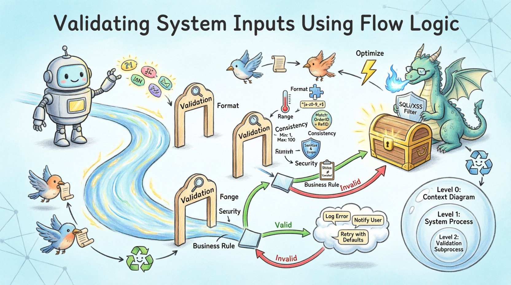
Types of Input Validation Rules 🛡️
Validation is not a monolithic concept. It encompasses several layers of scrutiny. Each layer serves a different purpose and requires different implementation strategies within the flow logic.
Validation Type
Purpose
Example Logic
Format Validation
Ensures data matches expected structure
Regex matching for phone numbers
Range Validation
Ensures data falls within numerical limits
Age must be between 18 and 120
Consistency Validation
Ensures data aligns with other inputs
End date must be after start date
Security Validation
Prevents malicious code injection
Sanitize HTML tags in text fields
Business Rule Validation
Ensures data fits operational constraints
Discount cannot exceed 50%
Integrating these rules into the flow logic requires careful sequencing. Security validation should generally occur early in the process to prevent expensive processing of malicious payloads. Format validation is usually the first step to ensure data types are correct before logical comparisons are made. Business rule validation often happens last, as it may depend on data that has already been normalized.
Handling Error Flows and Feedback Loops 🔄
A robust system does not just reject invalid data; it manages the rejection gracefully. This is where the “Invalid” branch of the flow logic comes into play. The error flow must lead to a mechanism that informs the user or system administrator about the issue without exposing sensitive internal details.
In the DFD, the error handling process should include:
Logging: Record the error details for debugging. This flow goes to an audit log data store.
Notification: Alert the user. This flow goes to the external entity (user interface).
Correction: Provide a mechanism to fix the data. This creates a feedback loop where the data returns to the input stage.
Feedback loops are critical for usability. If a user submits a form with an invalid email address, the system should allow them to correct it immediately. In flow terms, the data does not leave the input phase permanently. It is re-evaluated against the validation logic until it passes or the user cancels the action. This prevents dead ends in the user journey.
Error Logging and Audit Trails
Security and compliance often require that validation failures are recorded. Even if the input is rejected, the attempt itself might be a sign of an attack. Therefore, a separate data flow should exist from the validation process to an audit log. This flow captures timestamps, source IP addresses, and the nature of the failure. It operates independently of the main data flow to ensure that logging failures do not block legitimate processing.
Integrating Validation into Process Levels 🏗️
Data Flow Diagrams often exist at different levels of abstraction. Level 0 provides a high-level overview, while Level 1 and Level 2 break down specific processes. Validation logic must be consistent across these levels.
Level 0: System Boundary
At the highest level, validation is represented as a gate. The external entity sends data, and the system accepts or rejects it. The DFD shows the input and output boundaries. Any data that fails validation at this stage never enters the internal system.
Level 1: Process Breakdown
When decomposing the system, specific processes receive validation sub-flows. For example, a “User Registration” process might split into “Identity Check,” “Password Validation,” and “Contact Verification.” Each of these sub-processes has its own flow logic. The DFD at this level shows the internal data movement required to perform these checks.
Level 2: Detailed Logic
At the lowest level, the logic is fully defined. This is where the actual code structure is derived from the diagram. The flow logic here specifies the exact order of operations. For instance, checking if a username exists in the database must happen before checking if it is a valid format, to avoid leaking information about existing users.
Optimizing Performance During Validation ⚡
Validation logic adds computational overhead. Every check requires processing time. In high-volume systems, excessive validation can become a bottleneck. The DFD helps identify where optimization is needed.
Strategies for optimization include:
Early Exit: If a basic check fails (e.g., empty field), stop processing immediately. Do not run complex logic.
Caching: If validation depends on external data (e.g., checking a user ID against a list of banned accounts), cache that data to reduce database calls.
Asynchronous Processing: For non-critical validations, move the check to a background queue. This keeps the primary data flow fast.
When representing these optimizations in the DFD, use distinct data flows for synchronous and asynchronous tasks. This clarifies which validations block the user and which run in the background. It also helps in load testing scenarios where the system behavior under stress needs to be understood.
Security Implications of Flow Logic 🔒
Invalid input is a primary vector for attacks such as SQL injection, cross-site scripting, and buffer overflows. Flow logic designed for validation acts as a firewall. However, the design must be correct.
A common challenge in design is the assumption that input comes from a trusted source. In the DFD, every external entity should be treated as potentially hostile. The validation process must sanitize data before it interacts with databases or command lines. This sanitization is a specific process node in the diagram.
Additionally, flow logic must prevent information leakage. If a validation error reveals that a username exists, an attacker can use this to enumerate accounts. The error flow should provide generic messages (e.g., “Invalid credentials”) rather than specific reasons (e.g., “Username not found”). This nuance should be captured in the error handling process description.
Testing and Verification of Validation Flows ✅
Once the flow logic is designed, it must be verified. Testing involves sending data through the DFD paths to ensure the logic holds. This is often done using unit tests for individual validation rules and integration tests for the entire flow.
Test cases should cover:
Happy Path: Valid data passes all checks and reaches the data store.
Edge Cases: Data at the boundaries of ranges (e.g., minimum and maximum values).
Malformed Data: Data with incorrect types or unexpected characters.
Missing Data: Data where required fields are absent.
If the DFD is accurate, the test results should align with the visualized flows. If a test case fails in a way not predicted by the diagram, the DFD must be updated. This iterative process ensures the documentation remains a true reflection of the system behavior.
Conclusion on Structured Validation 📝
Validating system inputs using flow logic transforms a security requirement into a structural component of the architecture. By mapping validation rules within Data Flow Diagrams, teams can visualize where data is checked, how errors are handled, and how information moves through the system. This clarity reduces ambiguity, improves communication between designers and developers, and ultimately leads to more stable software. The integration of decision points, error flows, and security checks ensures that the system remains robust against the inevitable noise of the external world.
As systems grow in complexity, the reliance on structured flow logic becomes even more critical. It provides a blueprint for maintaining data integrity over time. By adhering to the principles outlined here, architects can build pipelines that trust nothing and verify everything, ensuring the longevity and reliability of the data ecosystem.