


Designing robust software systems requires clear documentation of how components interact. Communication diagrams offer a structured way to visualize object interactions and API flows without the rigid time constraints of sequence diagrams. This guide explores reusable templates for common API scenarios, helping architects and developers standardize their system design documentation.
When modeling API interactions, clarity is paramount. A well-constructed diagram reduces ambiguity during implementation and review. By adopting standardized patterns, teams can focus on business logic rather than reinventing the wheel for every interaction. This document details specific patterns, their structural requirements, and implementation considerations.
🧩 Understanding Communication Diagram Fundamentals
Before diving into specific patterns, it is essential to understand the core components of a communication diagram. Unlike sequence diagrams that emphasize time ordering, communication diagrams focus on the relationships between objects and the flow of messages.
Core Elements
- Participants: These represent the actors, services, or objects involved in the interaction. In an API context, these are typically client applications, gateway services, microservices, or external third-party systems.
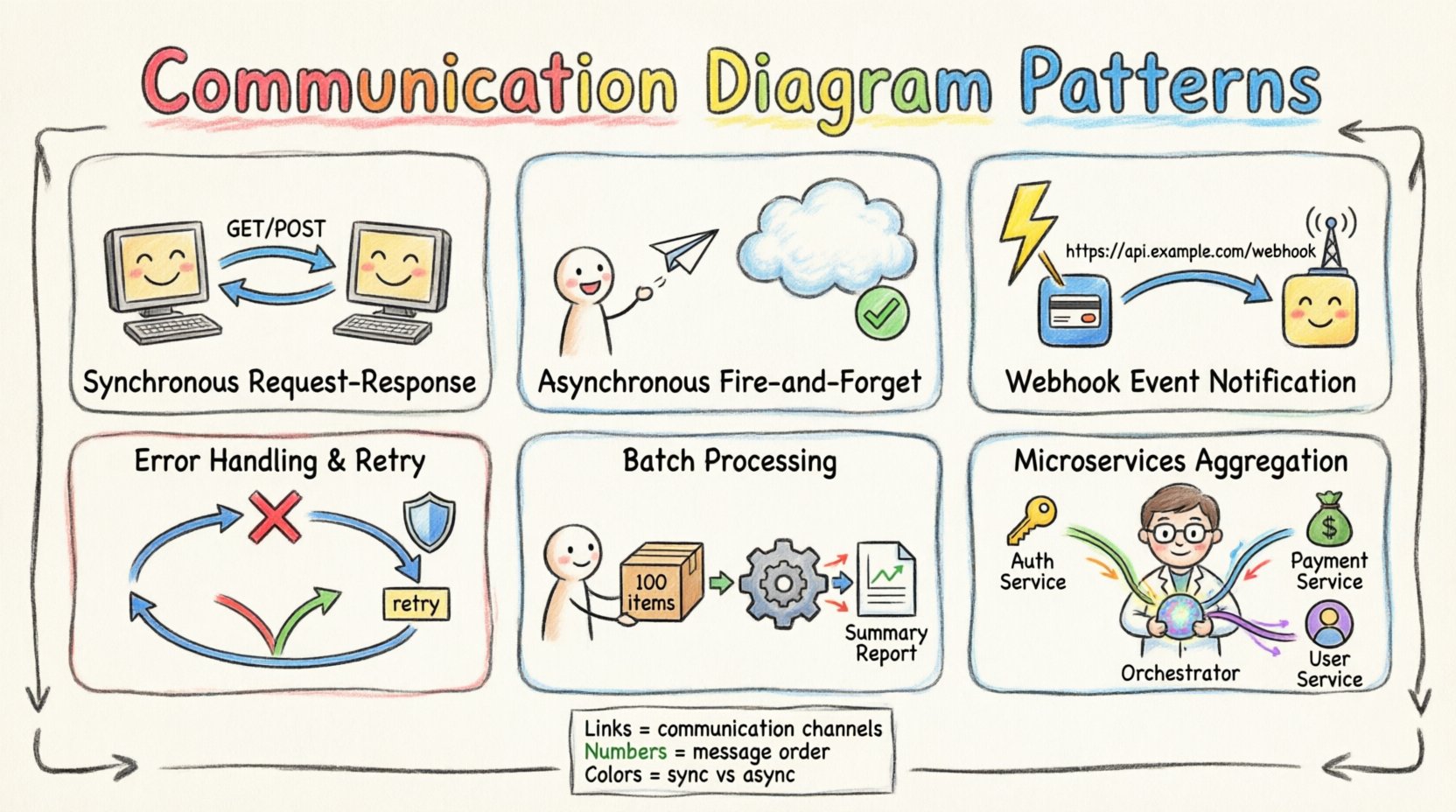
- Links: These define the connections between participants. They represent the communication channels, such as HTTP endpoints, message queues, or database connections.
- Messages: These are the requests or responses sent between participants. They include the operation name, parameters, and return values.
- Message Numbers: Sequential numbering indicates the order of message exchange, ensuring the flow is logical and traceable.
Using these elements effectively allows you to create diagrams that are both technically accurate and easy to read. The goal is to communicate the architecture without unnecessary complexity.
🔄 Pattern 1: Synchronous Request-Response
The Request-Response pattern is the most common interaction model in RESTful APIs. It involves a client initiating a call and waiting for an immediate reply from the server before proceeding.
Diagram Structure
- Initiator: The Client Application or API Gateway.
- Responder: The Target Microservice or API Endpoint.
- Flow: The message flows from Initiator to Responder, followed by a return message from Responder to Initiator.
Implementation Details
- HTTP Methods: Typically uses GET, POST, PUT, or DELETE.
- Latency: The client is blocked until the response arrives. This impacts user experience in high-latency networks.
- State Management: The server often maintains session state or processes stateless transactions based on headers.
- Error Handling: If the server fails, the client must handle the error response and decide whether to retry or fail gracefully.
When documenting this pattern, ensure you label the messages with the specific HTTP method and the expected payload format. This reduces confusion during code implementation.
⚡ Pattern 2: Asynchronous Fire-and-Forget
In some scenarios, the client does not require an immediate response. This pattern is useful for logging, notifications, or background processing tasks where blocking the client is undesirable.
Diagram Structure
- Initiator: The Client Application.
- Receiver: The Message Broker or Background Service.
- Flow: The message is sent from Initiator to Receiver. No return message is drawn, or a simple acknowledgment is shown.
Implementation Details
- Message Queues: Systems like RabbitMQ, Kafka, or internal queues handle the decoupling.
- Idempotency: Since the client does not wait, the receiver must handle duplicate messages if the sender retries.
- Confirmation: Optional acknowledgment messages can be added to indicate successful receipt without processing.
- Reliability: Ensures data is not lost even if the receiver is temporarily unavailable.
This pattern improves system responsiveness. The client submits the task and moves on, while the receiver processes the workload at its own pace.
📡 Pattern 3: Event Notification (Webhooks)
Webhooks allow one system to automatically push data to another when specific events occur. This is the reverse of the traditional polling model.
Diagram Structure
- Trigger Source: The System generating the event (e.g., Payment Gateway).
- Receiver: The Client Application configured to listen for events.
- Flow: The Source detects an event and sends an HTTP POST to the Receiver’s webhook URL.
Implementation Details
- Security: Signatures or tokens must verify the authenticity of the incoming request.
- Retry Logic: The Source should retry failed deliveries based on status codes returned by the Receiver.
- Payload Structure: Standardized JSON schemas ensure the Receiver can parse the data correctly.
- Idempotency: The Receiver must handle duplicate notifications if the Source retries.
Using this pattern reduces the load on the source system, as it does not need to poll the receiver continuously. It shifts the responsibility of data retrieval to the event trigger.
🧪 Pattern 4: Error Handling and Retry Logic
Network failures and service outages are inevitable. A communication diagram must account for failure paths to be truly useful.
Diagram Structure
- Primary Flow: Successful message exchange.
- Error Flow: Divergent paths showing timeout, rejection, or exception scenarios.
- Retry Loop: A cycle showing the message returning to the sender for retransmission.
Implementation Details
- Timeouts: Define clear time limits for waiting on a response.
- Backoff Strategies: Exponential backoff prevents overwhelming a recovering service.
- Circuit Breakers: Prevent repeated calls to a failing service to allow it time to recover.
- Dead Letter Queues: Messages that fail all retries are moved to a separate queue for analysis.
Visualizing these paths helps developers anticipate edge cases. It ensures that the system degrades gracefully rather than crashing unexpectedly.
📦 Pattern 5: Batch Processing
Processing large datasets one item at a time is inefficient. Batch processing groups multiple requests into a single transaction.
Diagram Structure
- Client: Sends a single request containing an array of items.
- Processor: Iterates through the array and processes items individually or in sub-groups.
- Response: Returns a summary of success and failure for the batch.
Implementation Details
- Size Limits: Enforce maximum payload sizes to prevent memory issues.
- Partial Success: The response should indicate which specific items succeeded and which failed.
- Transaction Management: Determine if the batch is atomic (all succeed or all fail) or non-atomic.
- Timeouts: Batch operations may take longer, requiring adjusted timeout thresholds.
This pattern reduces network overhead and improves throughput. However, it introduces complexity in error reporting and rollback strategies.
🔄 Pattern 6: Aggregation and Microservices Collaboration
Modern architectures often require data from multiple services to answer a single client request. This pattern involves an API Gateway or Orchestrator collecting data from downstream services.
Diagram Structure
- Client: Initiates the request.
- Orchestrator: The entry point that coordinates calls.
- Downstream Services: Multiple independent services providing specific data.
- Flow: Orchestrator calls Service A and Service B, merges results, and returns to Client.
Implementation Details
- Concurrency: Calls to downstream services can often happen in parallel to reduce latency.
- Data Consistency: Data from different services may have slightly different timestamps or states.
- Graceful Degradation: If one service fails, the Orchestrator might return partial data or a cached version.
- Security: The Orchestrator must validate permissions for all downstream calls.
This pattern simplifies the client interface but adds complexity to the backend orchestration logic.
⚖️ Comparison: Communication vs. Sequence Diagrams
Choosing between diagram types depends on the information you need to convey. The following table outlines the differences.
| Feature | Communication Diagram | Sequence Diagram |
|---|---|---|
| Focus | Object relationships and links | Time ordering and message flow |
| Layout | Flexible, spatial arrangement | Vertical timeline |
| Complexity | Can become cluttered with many links | Clearer for deep nesting |
| Use Case | High-level API interaction overview | Detailed algorithmic flow |
| Message Numbers | Required for ordering | Implied by vertical position |
🛠️ Best Practices for Creating Templates
To maintain consistency across your documentation, follow these guidelines when creating templates.
- Standardize Naming Conventions: Use consistent names for participants (e.g., “Client,” “Gateway,” “Database”) across all diagrams.
- Define Message Formats: Specify the payload type (JSON, XML, Protobuf) in the message labels.
- Color Coding: Use colors to distinguish between internal and external systems, or between synchronous and asynchronous flows.
- Version Control: Treat diagrams as code. Store them in your repository alongside the source code to track changes.
- Keep it Updated: Diagrams become stale quickly. Review them during code reviews or sprint retrospectives.
- Focus on Logic: Do not clutter diagrams with every single parameter. Focus on the interaction flow and key data points.
📝 Creating Reusable Templates
Building a library of templates accelerates the design process. Here is how to structure your template library.
Template Inventory
- Entry Points: Define how external traffic enters the system.
- Core Services: Standardize the interaction between primary business services.
- Infrastructure: Document interactions with databases, caches, and message brokers.
- Security: Include patterns for authentication and authorization flows.
Template Maintenance
- Review Cycle: Schedule quarterly reviews of the template library.
- Feedback Loop: Encourage developers to suggest improvements based on implementation friction.
- Documentation: Write a brief guide explaining when to use each template.
🎯 Conclusion
Effective system design relies on clear communication. Communication diagrams provide a powerful tool for visualizing API interactions and service dependencies. By utilizing the patterns outlined in this guide—such as synchronous requests, asynchronous notifications, and batch processing—teams can create consistent, maintainable documentation.
Adopting these templates does not guarantee perfect systems, but it significantly reduces the cognitive load on developers. It ensures that everyone understands how data moves through the architecture. Regular maintenance and adherence to best practices will keep your documentation relevant and useful throughout the lifecycle of the software.
Start by selecting the patterns that match your current architecture. Integrate them into your design workflow. Over time, these visual standards will become second nature, improving collaboration and reducing implementation errors.