


Designing a robust state machine is one of the most critical tasks in system architecture. When implemented correctly, state diagrams provide clarity, predictability, and maintainability. However, when logic is flawed, the system can enter a state where no further progress is possible. This is known as a deadlock. In a state machine diagram, a deadlock occurs when the system reaches a state from which no valid transition exists, halting execution indefinitely. ⏸️
This guide explores the mechanics of state machine design, focusing specifically on identifying and preventing deadlocks. We will cover transition guards, entry and exit actions, concurrent regions, and validation strategies. By following these structured approaches, you can ensure your state diagrams remain resilient under various conditions. 🔒
🧠 Understanding State Machine Deadlocks
A deadlock in a finite state machine (FSM) represents a logical halt. Unlike a runtime error that might crash the application, a deadlock often results in the system appearing to freeze while still running. The engine is active, but it cannot execute any commands because the current state lacks outgoing transitions that satisfy the trigger conditions. 🔍
To design effectively, one must understand the anatomy of a deadlock scenario. It is rarely caused by a single missing line of code. Instead, it is often the result of complex interactions between multiple states, guards, and external events. Below are the core characteristics of a deadlock state:
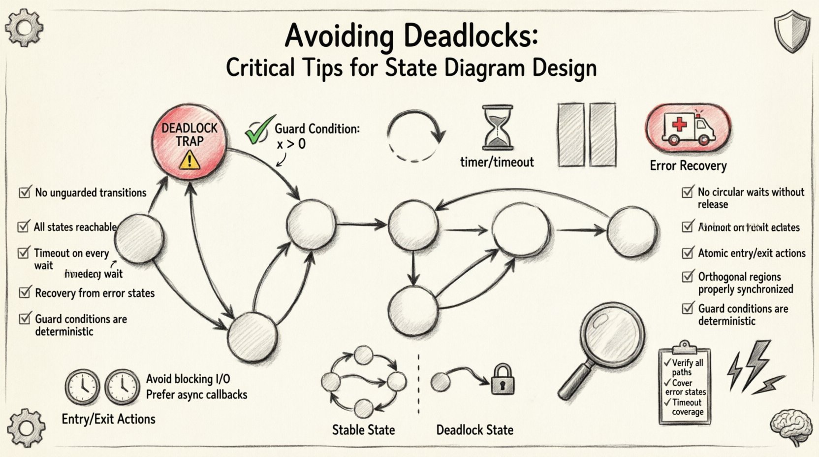
- No Outgoing Transitions: The state has no arrows leading out of it.
- Unreachable Transitions: All outgoing arrows have guard conditions that can never be true given the current data.
- Missing Default Paths: There is no fallback transition to handle unexpected inputs.
- Resource Holding: The system holds a resource (like a lock or connection) but waits for another condition that will never occur.
Preventing these scenarios requires a proactive design philosophy rather than reactive debugging. Let us examine the root causes in detail. 📉
⚠️ Common Causes of Deadlocks in State Design
Deadlocks are not random accidents; they are predictable outcomes of specific design choices. Understanding these patterns helps you avoid them before they impact production. Here are the primary culprits behind state machine stalling.
1. Missing Transition Guards
When designing transitions, every arrow leaving a state represents a possible path forward. If a state has multiple possible inputs (events), but only some are mapped to transitions, the system halts when an unmapped event occurs. This is often called a “trap” state. ❌
- The Problem: A state machine expects specific triggers. If an unexpected trigger arrives, and no transition handles it, the system stays put.
- The Fix: Ensure every state accounts for all defined events, or implement a global default handler to catch unexpected inputs.
2. Conflicting Guard Conditions
Guard conditions are boolean expressions that must evaluate to true for a transition to fire. A common error occurs when two transitions share the same source state and event, but their guard conditions are mutually exclusive or cover no possible scenario. 🧩
- The Problem: You define transition A (if score > 10) and transition B (if score < 5). What happens if the score is exactly 10? If logic is strict, it might fail both.
- The Fix: Review guard conditions for edge cases. Ensure the union of all guard conditions for a specific event covers the entire input domain.
3. Circular Dependencies
In complex systems, states may depend on the status of other states or external processes. If State A waits for State B to finish, and State B waits for State A to acknowledge, neither moves. This is a classic synchronization deadlock. ⏳
- The Problem: Logic is entangled in a way that requires mutual acknowledgment before progress.
- The Fix: Break the cycle by introducing timeouts or allowing one process to proceed without the other’s immediate confirmation.
4. Improper Handling of History States
History states allow a system to remember its previous state upon re-entry. If not implemented correctly, a history state can point to a state that is no longer valid or has been deleted. 🔄
- The Problem: The machine attempts to transition to a historical state that no longer exists or is inaccessible.
- The Fix: Validate that historical targets are still active when the machine restarts or resets.
🛡️ Design Patterns to Prevent Stalling
Once you understand the risks, you can apply specific patterns to mitigate them. These patterns are not software-specific; they apply to any modeling language or implementation framework. 🛠️
1. The Default State Pattern
Every state machine should have a defined entry point. This is typically the initial state. However, beyond the initial state, every other state should ideally have a default path. If an event does not match a specific condition, the system should fall back to a safe default behavior. 📍
- Implementation: Create a “catch-all” transition for every state that handles unknown events gracefully.
- Benefit: Prevents the system from entering an undefined state when an unexpected input occurs.
2. The Timeout Guard Pattern
Sometimes a state must wait for an external event that might never come. To prevent indefinite waiting, you can introduce a timer. If the event does not arrive within a specified duration, a timeout transition fires. ⏱️
- Implementation: Add a transition triggered by a time-based event (e.g., “Timer Expired”).
- Benefit: Ensures the system always moves forward, even if the primary condition is not met.
3. The Parallel State Pattern
In complex workflows, a single state cannot capture all concurrent activities. Orthogonal regions allow you to split a state into multiple independent sub-states. This reduces the complexity of transition guards. ⚡
- Implementation: Use composite states with multiple regions that run simultaneously.
- Benefit: Simplifies logic by separating concerns. If one region deadlocks, the other can still function or report the error.
4. The Error Recovery State
Design a specific state dedicated to handling errors. If the system detects an anomaly, it transitions to this state immediately. From here, it can attempt to reset, retry, or alert an operator. 🚑
- Implementation: Add a dedicated “Error” or “Recovery” state accessible from multiple points.
- Benefit: Isolates the failure and provides a clear path to recovery, rather than leaving the system in a broken state.
📊 Comparison: Deadlock vs. Stable State
To visualize the difference between a healthy state and a deadlock, consider the following comparison table. This highlights the structural differences in design.
| Feature | Stable State | Deadlock State |
|---|---|---|
| Transitions | At least one valid outgoing transition exists. | No outgoing transitions satisfy current conditions. |
| Guard Logic | Guards cover all relevant input scenarios. | Guards are mutually exclusive or incomplete. |
| Event Handling | Events trigger expected actions. | Events are ignored or cause a halt. |
| Recovery | System self-corrects or proceeds to next phase. | System requires external intervention to restart. |
🧪 Validation and Testing Strategies
Design is only half the battle. You must validate the diagram to ensure it holds up under stress. Testing state machines requires a different approach than testing standard functions. 🧪
1. Model Checking
Model checking is a formal verification method. It mathematically proves that a state machine satisfies certain properties, such as “no state is reachable where a deadlock exists.” This is highly effective for critical systems. 🔢
- Technique: Use formal methods tools to traverse the entire state space.
- Outcome: A mathematical guarantee that the system cannot enter a deadlock state.
2. State Coverage Testing
Ensure that every state and every transition is tested at least once. This is known as state coverage. If a state is not tested, you cannot know if it contains a hidden deadlock condition. 🎯
- Technique: Write test cases that force the system into every defined state.
- Outcome: Verification that transitions fire correctly from every entry point.
3. Stress Testing Inputs
Send invalid, null, or unexpected inputs to the system. A robust state machine should not crash or hang when given bad data. It should either reject the input or transition to a safe state. 🌪️
- Technique: Generate random or boundary inputs and observe behavior.
- Outcome: Identification of edge cases that lead to deadlocks.
4. Static Analysis
Before running the code, analyze the diagram structure. Look for states with no outgoing arrows. Look for loops that never terminate. Tools can often detect these patterns automatically. 🔎
- Technique: Run linting or static analysis scripts on the state definition files.
- Outcome: Early detection of structural errors.
🔄 Handling Concurrency and Parallel States
Concurrency adds complexity. When multiple regions operate simultaneously, deadlocks can arise from synchronization issues. You must ensure that parallel paths do not block each other. 🏗️
1. Independent Regions
Ensure that parallel states are truly independent. If State A in Region 1 needs data from State B in Region 2, you introduce a dependency. This dependency can become a bottleneck. 🚧
- Best Practice: Minimize data sharing between orthogonal regions.
- Alternative: Use an event bus to communicate between regions without direct blocking.
2. Synchronization Points
Sometimes states must synchronize. For example, Region A must finish before Region B starts. If you implement this manually, you risk deadlock. Use built-in synchronization constructs provided by your framework. ⚙️
- Best Practice: Avoid manual locking mechanisms unless absolutely necessary.
- Alternative: Use join states that wait for all incoming paths to complete naturally.
⚙️ Entry and Exit Actions
Entry and exit actions are code snippets that run when entering or leaving a state. These are common sources of subtle deadlocks. ⚠️
1. Blocking Entry Actions
If an entry action performs a long-running task (like a network request) without a timeout, the system cannot leave that state until the task completes. If the task hangs, the state machine hangs. 🕸️
- Best Practice: Keep entry actions lightweight and non-blocking.
- Alternative: Offload heavy tasks to background workers and transition to a “Processing” state.
2. Infinite Loops in Exit Actions
An exit action should never trigger a transition that leads back to the same state immediately. This creates a loop that consumes resources without progress. 🔄
- Best Practice: Ensure exit actions do not re-trigger the same state transition.
- Alternative: Use flags to prevent recursive triggering of actions.
📝 Review Checklist for State Diagrams
Before deploying a state machine, run through this checklist. It covers the critical areas where deadlocks typically hide. ✅
| Check Item | Pass / Fail | Notes |
|---|---|---|
| Are all states reachable from the initial state? | ||
| Does every state have at least one outgoing transition? | ||
| Are all guard conditions logically sound (no gaps)? | ||
| Are there timeout mechanisms for waiting states? | ||
| Do parallel regions avoid direct data dependencies? | ||
| Is there a global error recovery state? | ||
| Have entry actions been tested for blocking behavior? |
🔍 Deep Dive: Edge Case Scenarios
Even with good design, edge cases can slip through. Here are specific scenarios where deadlocks often manifest in production environments. 🌐
1. The Race Condition Trap
When two events occur simultaneously, the order of processing matters. If the state machine processes Event A before Event B, it might take a path that deadlocks. If it processes B before A, it might succeed. ⚡
- Mitigation: Queue events and process them sequentially. Ensure the order of events does not affect the final state validity.
2. The Resource Exhaustion Trap
A state might wait for a resource (like a database connection). If the pool is exhausted, the wait is infinite. This looks like a deadlock but is actually a resource issue. 💾
- Mitigation: Implement connection timeouts and fallback states that degrade functionality gracefully.
3. The Configuration Drift Trap
The diagram might be designed for State A, but the configuration file specifies State B. If the transition logic relies on configuration values that are missing, the system stalls. 📄
- Mitigation: Validate configuration against the state diagram schema at startup.
🚀 Final Considerations for Robust Design
Building a state machine that resists deadlocks is about discipline. It requires anticipating failure modes and designing paths around them. By focusing on clear transitions, comprehensive guard logic, and robust error handling, you create systems that are resilient to change. 🛡️
Remember that state diagrams are living documents. As requirements change, the diagram must evolve. Regular refactoring and review sessions ensure that new features do not introduce old bugs. Keep the model simple, keep the logic explicit, and keep the recovery paths clear. 🔄
When you prioritize stability over speed in the design phase, you save significant time in maintenance later. A well-designed state machine is the backbone of reliable software behavior. Invest the effort in the design, and the system will perform consistently. 📈