


The backbone of reliable software systems lies in how we model behavior over time. State diagrams, often referred to as state machine diagrams, have served as a critical tool for developers and architects for decades. They provide a visual representation of the various states an object or system can occupy and the transitions that occur between them. As software architectures shift from monolithic structures to distributed, event-driven ecosystems, the role of state modeling is undergoing a significant transformation.
This guide examines the trajectory of state diagram evolution, exploring how traditional finite state machine concepts adapt to contemporary challenges like concurrency, scalability, and automated verification. We will analyze the shift from static modeling to dynamic runtime visualization and discuss the implications for long-term system maintainability.
🏛️ The Foundations: Classical State Modeling
Before diving into future trends, it is essential to understand the baseline. Classical state diagrams are rooted in formal logic and automata theory. They define a system as a set of states, events, and transitions. In the early days of software engineering, these diagrams were primarily used to describe the behavior of single-threaded processes or hardware logic.
- Finite State Machines (FSM): A mathematical model of computation where a system can exist in one state at a time. Transitions occur based on specific inputs.
- UML State Machine Diagrams: An extension of FSMs that introduced features like hierarchical states, concurrent states (orthogonal regions), and history states. This allowed for more complex logic representation within a single diagram.
- Moore vs. Mealy Machines: A fundamental distinction in how outputs are generated. Moore machines produce outputs based on the current state, while Mealy machines base outputs on the current state and input.
These foundational models provided clarity. However, as systems grew in complexity, the static nature of these diagrams began to show limitations when applied to modern, cloud-native environments.
☁️ The Distributed Challenge: State in Microservices
The move toward microservices architecture introduced a paradigm shift. In a monolith, state is often stored in a local memory or a shared database. In a distributed system, state is fragmented across multiple services. This fragmentation complicates the visualization and management of state transitions.
🔗 Eventual Consistency and State
In distributed environments, immediate consistency is often traded for availability and partition tolerance. State diagrams must now account for eventual consistency. A transition that was once atomic may now span multiple services over time.
- Temporal Complexity: Transitions are no longer instantaneous. Delays, retries, and partial failures must be modeled.
- Compensating Transactions: If a state transition fails halfway through, the system needs a defined path to revert. This introduces “compensation states” that were rarely needed in monolithic designs.
- Choreography vs. Orchestration: State management can be decentralized (choreography) or centralized (orchestration). Diagrams must reflect who controls the flow of state changes.
📊 Comparing State Management Approaches
| Feature | Traditional Monolith | Modern Distributed System |
|---|---|---|
| State Location | Local Memory / Shared DB | Distributed Cache / Event Log |
| Transition Latency | Nanoseconds | Milliseconds to Seconds |
| Failure Handling | Rollback / Exception | Retry / Saga / Compensation |
| Visibility | Single Thread | Multiple Concurrent Streams |
| Diagram Scope | Single Component | System-Wide Workflow |
🧩 Model-Driven Engineering and Code Generation
One of the most significant evolutions in state diagram usage is the move toward Model-Driven Engineering (MDE). Instead of writing code and then documenting it with a diagram, developers are beginning to define the diagram first and generate the implementation code automatically.
This approach offers several advantages:
- Single Source of Truth: The diagram becomes the specification. The code is derived from it, reducing the risk of documentation drift.
- Validation at Design Time: Logic errors can be caught before compilation. Deadlocks and unreachable states can be identified during the modeling phase.
- Language Agnosticism: The same state machine model can be compiled into different programming languages, facilitating polyglot persistence and microservice development.
However, this requires a robust toolchain. The abstraction layer must be precise. If the generated code is verbose or inefficient, the benefits of modeling diminish. The focus is shifting toward high-fidelity models that map cleanly to runtime execution contexts.
🤖 AI and Automation in State Modeling
The integration of artificial intelligence into software development processes is influencing how state diagrams are created and maintained. Large Language Models (LLMs) are increasingly capable of interpreting natural language requirements and converting them into structured state machine definitions.
🔍 Automated Diagram Generation
Developers can input a set of user stories or functional requirements. The AI analyzes the text to identify potential states and transitions. This does not replace human oversight but accelerates the initial drafting phase.
- Pattern Recognition: AI can suggest standard patterns, such as retry loops or timeout states, based on historical data.
- Refinement: AI can help refactor complex diagrams, breaking down monolithic states into smaller, manageable sub-states.
- Code Translation: Converting a visual diagram into boilerplate code for specific runtime environments.
🧠 Predictive Analysis
Future systems may utilize AI to predict state transitions based on usage patterns. If a system detects a high probability of a specific state sequence, it can pre-fetch resources or optimize the transition path. This moves state management from reactive to proactive.
🛡️ Verification and Formal Methods
In critical systems—such as healthcare, finance, or autonomous control—the cost of a state error is too high to rely on testing alone. Formal verification ensures that the state diagram meets specific mathematical properties.
- Reachability Analysis: Ensuring every state can be reached from the initial state without violating constraints.
- Deadlock Detection: Mathematically proving that the system cannot enter a state where no transitions are possible.
- Invariant Checking: Verifying that certain conditions (invariants) hold true regardless of the current state.
As tools improve, formal verification is becoming more accessible to general software engineering teams, not just those in safety-critical industries. This trend pushes state diagrams to be more rigorous, treating them as specifications that must be proven correct rather than just documentation.
🎨 Visual Debugging and Runtime Observability
A significant gap exists between the static design diagram and the dynamic runtime behavior. Future state diagram tools are bridging this gap through live observability.
📡 Live State Tracking
Modern monitoring systems can overlay the actual execution path of a system onto the original state diagram. This allows architects to see which paths are actually being used in production.
- Heatmaps: Visualizing the frequency of transitions. Rarely used states can be identified for removal.
- Anomaly Detection: Highlighting transitions that occur outside the expected model. This is crucial for security auditing and detecting logic bugs.
- Temporal Correlation: Linking state transitions to specific logs or metrics to understand performance bottlenecks.
🔒 Security Implications of State Management
State diagrams are not just about logic flow; they are about security boundaries. Improper state management is a leading cause of vulnerabilities, such as insecure direct object references or broken access control.
🚧 State-Based Access Control
Permissions should often be tied to the state of the system. For example, a document in the “Draft” state may be editable by the author, but once it moves to “Published,” only admins can modify it. State diagrams help visualize these permission gates.
- State Transition Attacks: Attackers may attempt to force a transition to a privileged state without completing intermediate steps. Diagrams help identify these gaps.
- Session Management: State diagrams define the lifecycle of user sessions, including login, idle timeouts, and logout. Clear modeling prevents session fixation vulnerabilities.
- Audit Trails: Every state transition should ideally be logged. The diagram defines the events that trigger these logs.
🚀 Emerging Standards and Protocols
The ecosystem surrounding state modeling is evolving. New standards are emerging to facilitate interoperability between different modeling tools and runtime engines.
- JSON-Based State Definitions: Moving away from proprietary binary formats to text-based standards like JSON or YAML allows for better version control and collaboration.
- WebAssembly (WASM): As WASM gains traction, state machines can be compiled to run efficiently in the browser or serverless environments, enabling consistent behavior across platforms.
- GraphQL Subscriptions: State changes can be pushed to clients in real-time via subscriptions. The state diagram defines the events that trigger these subscriptions.
🧭 Best Practices for Future-Proofing State Models
To remain effective as architecture evolves, state modeling practices must adapt. Here are key principles for maintaining robust state diagrams in modern contexts.
1. Keep States Atomic
Avoid creating states that represent too much complexity. If a state involves multiple concurrent processes, split it into orthogonal regions. This improves readability and debugging.
2. Define Clear Entry and Exit Actions
Ensure every transition has defined entry and exit logic. Ambiguity here leads to race conditions in implementation. Use guard conditions to prevent invalid transitions.
3. Version Your Models
Just like code, state diagrams must be versioned. Changes in business logic should result in a new version of the model, allowing for backward compatibility during deployment.
4. Separate Concerns
Do not mix state logic with data persistence logic. The diagram should describe behavior, not storage. This separation allows the underlying data layer to change without altering the flow control model.
5. Embrace Asynchrony
Design diagrams that assume delays. Network calls, database writes, and user inputs are not instantaneous. Model the “waiting” states explicitly rather than assuming immediate completion.
📈 The Path Forward
The evolution of state diagrams is not about replacing them but augmenting them. The core logic of the state machine remains valid, but the tools surrounding it are becoming more powerful.
We are moving toward a future where:
- Design and implementation are tightly coupled through code generation.
- Runtime observability feeds back into the design model for continuous improvement.
- Formal verification ensures correctness in high-stakes environments.
- AI assists in generating and validating the complexity of distributed workflows.
Architects who understand the nuances of state evolution will be better equipped to build systems that are resilient, maintainable, and secure. The state diagram remains a vital artifact, but its role has expanded from a static blueprint to a dynamic component of the software lifecycle.
🧪 Testing State Machine Logic
Testing state machines requires a different approach than standard unit testing. You must verify not just the output of a function, but the resulting state and the validity of the transition.
- State Coverage: Ensure every state is reached during testing.
- Transition Coverage: Verify that every arrow on the diagram is traversed.
- Boundary Conditions: Test transitions that occur at the edges of validity (e.g., maximum retry attempts).
- Concurrent Execution: Test scenarios where multiple events arrive simultaneously to ensure the machine handles race conditions correctly.
Automated testing frameworks for state machines are becoming more prevalent. These tools allow developers to define a sequence of events and assert the final state, making regression testing for complex logic feasible.
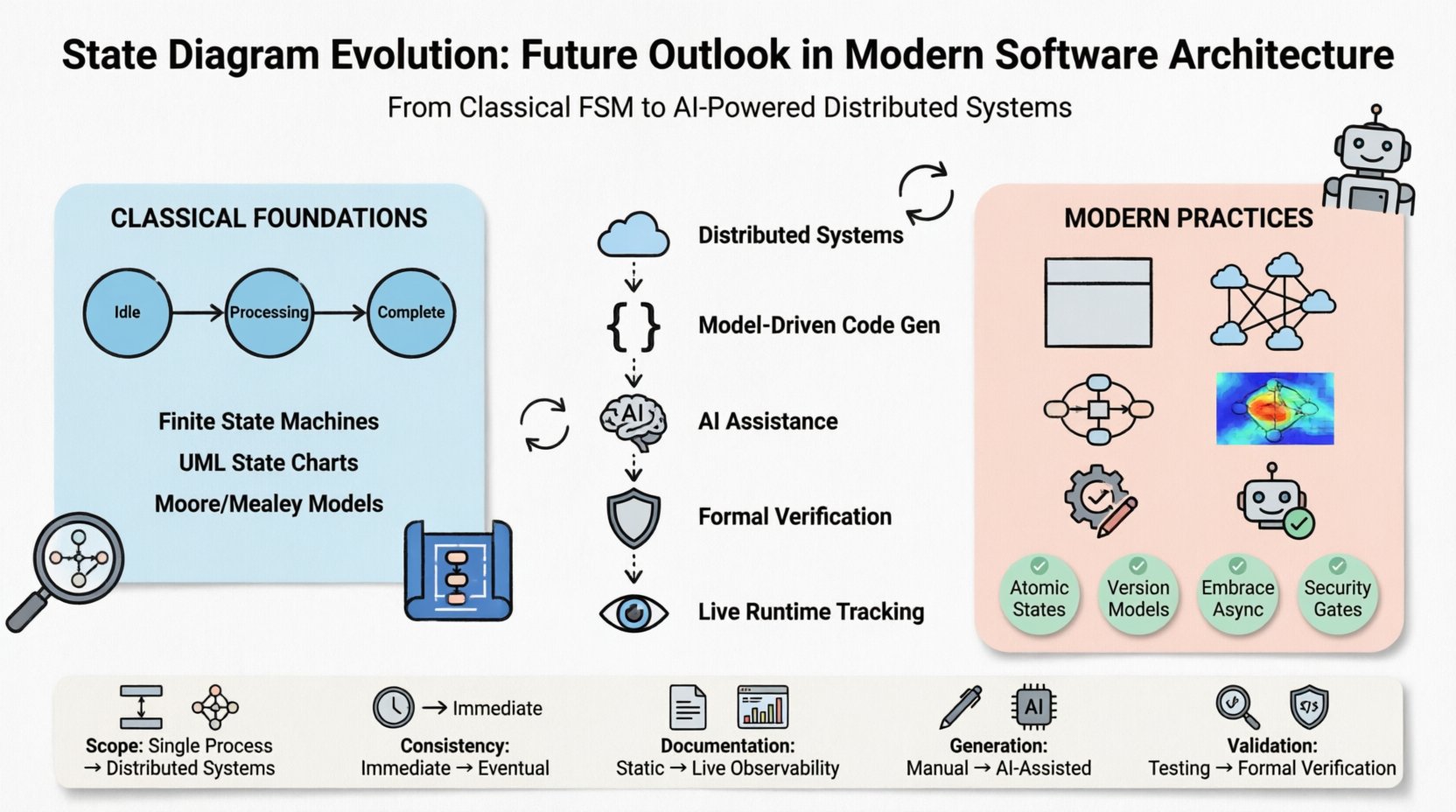
📝 Summary of Key Shifts
To encapsulate the major shifts discussed, consider the following summary of the evolution from past to future.
| Aspect | Past Focus | Future Focus |
|---|---|---|
| Scope | Single Process | Distributed Systems |
| Consistency | Immediate | Eventual / Causal |
| Documentation | Static Diagrams | Live Observability |
| Generation | Manual Coding | Model-Driven / AI |
| Validation | Manual Testing | Formal Verification |
By acknowledging these shifts, engineering teams can better prepare their architecture strategies. The state diagram is no longer just a drawing; it is a contract between the design intent and the runtime reality. As software continues to become more complex, the discipline of modeling state accurately becomes a competitive advantage.
Investing time in refining state modeling practices today pays dividends in system stability tomorrow. The tools are maturing, the theories are solid, and the need for clear behavioral specifications is greater than ever.
🔍 Final Thoughts on Architecture
The journey of state diagrams from simple logic charts to complex distributed models mirrors the broader journey of software engineering itself. We have moved from isolated components to interconnected ecosystems. Through this transition, the need for clarity has not diminished; it has intensified.
Developers and architects who prioritize state modeling will find themselves better equipped to handle the intricacies of modern infrastructure. Whether dealing with serverless functions, containerized microservices, or edge computing nodes, the principles of state management remain constant. The difference lies in the execution environment and the tools used to visualize it.
As we look ahead, the integration of these models with operational intelligence will define the next generation of reliable software systems. The state diagram remains the map, but now it is a live map, constantly updated by the terrain it traverses.