Data Flow Diagrams (DFDs) serve as the blueprint for understanding how information moves through a system. At the heart of these diagrams lies a critical component: the External Entity. These elements define the boundary between the system being modeled and the outside world. Without a clear definition of these entities, the flow of data lacks context, and the system architecture becomes ambiguous. This guide explores the mechanics, definitions, and modeling strategies surrounding external entities to ensure precise system documentation.
What Defines an External Entity? 🎯
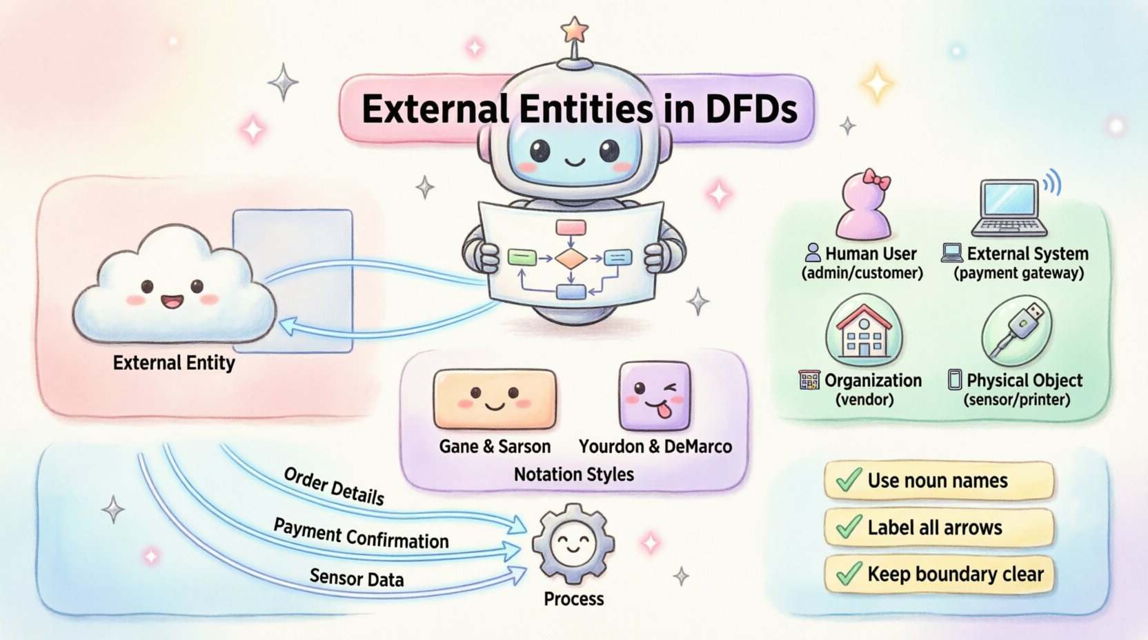
An external entity, often referred to as an actor, source, or sink, represents a person, organization, or system that interacts with the system under analysis. They exist outside the boundary of the system but are necessary for the system to function. In the context of a DFD, the system boundary separates internal processes from external influences. Anything that provides input data or receives output data falls into this category.
Think of an external entity as a participant that does not process data within the specific scope of the current model. For instance, in a library management system, the librarian is an external entity. They input book details and receive loan records, but the internal logic of calculating fines or reserving books happens inside the system, not within the librarian themselves. The entity initiates the interaction or receives the result.
- Source: An entity that originates data flowing into the system.
- Sink: An entity that receives data flowing out of the system.
- Both: An entity can act as both a source and a sink, interacting in multiple ways.
Identifying these correctly is foundational. If an entity is placed incorrectly, the data flow arrows will point to the wrong places, leading to confusion during the development or implementation phase.
The Role of Boundaries 🚧
The concept of a system boundary is central to defining external entities. A DFD is not a diagram of the entire universe; it is a focused view of a specific system. The boundary is the line drawn around the processes that transform data. Everything inside this line is part of the system. Everything outside is external.
When modeling, you must decide what falls inside and what falls outside. This decision depends on the scope of the project. For example, in a banking application, the customer is an external entity. However, if the scope expands to include the entire banking infrastructure, the customer might become internal to a broader system, though typically, users remain external to the software system itself.
The boundary ensures that the model remains manageable. It prevents the diagram from becoming an endless chain of external dependencies. By clearly marking the boundary, developers know exactly which processes are internal and which data sources must be queried from outside.
Types of External Actors 👥
External entities are not limited to human users. They encompass various forms of interaction points. Recognizing the type of entity helps in understanding the nature of the data exchange.
| Entity Type |
Description |
Example |
| Human User |
A person who interacts with the system directly. |
Admin, Customer, Employee |
| External System |
Another software application or hardware device. |
Payment Gateway, CRM Tool |
| Organization |
A company or department that sends or receives data. |
Vendor, Regulatory Agency |
| Physical Object |
A tangible item that triggers data entry or receives output. |
Scanner, Printer, Sensor |
Understanding these distinctions is vital for integration planning. A human user might require a graphical interface, whereas an external system might require an API or file transfer protocol. The DFD captures the logical flow, but knowing the entity type informs the technical implementation.
Visual Notation Standards 📐
There are two primary notations used for DFDs. Each uses different shapes to represent external entities. It is important to choose one standard and stick to it throughout the documentation to avoid confusion.
Gane and Sarson Notation
In this style, external entities are represented by a rectangle. The name of the entity is placed inside the box. This notation is widely used in enterprise environments. The rectangle suggests a container or a distinct organizational unit.
Yourdon and DeMarco Notation
This style uses a square shape for external entities. While visually similar, the emphasis is slightly different. Some teams prefer the square for its distinctiveness against the rounded rectangles used for processes. Regardless of the shape, the function remains identical: it marks the edge of the system.
Consistency is key. Mixing notations in a single diagram can lead to misinterpretation. If a team standardizes on Gane and Sarson, all diagrams should use rectangles for entities. If the project switches notation midway, it requires a comprehensive review of all documentation.
Connecting Entities to Processes 🔗
Data flows connect entities to processes. These flows represent the movement of data, not the movement of physical objects. An arrow drawn from an external entity to a process indicates that the entity is providing information required by that process.
Conversely, an arrow from a process to an external entity indicates that the system is sending information back to the source. It is important to remember that data cannot flow directly from one external entity to another without passing through at least one process. This ensures that the system performs some form of transformation or validation on the data.
- Input Flow: Data entering the system from an entity.
- Output Flow: Data leaving the system to an entity.
- Validation: The process often checks the incoming data before storing or processing it further.
Every arrow must have a label. This label describes the data being moved. For example, a label might say “Order Details” or “Payment Confirmation.” Vague labels like “Data” or “Info” reduce the clarity of the diagram and hinder understanding during audits or reviews.
Naming Conventions and Clarity 🏷️
Naming external entities correctly is a best practice that aids long-term maintenance. Names should be nouns, not verbs. An entity is a thing or a person, not an action. For example, use “Customer” instead of “Customer Service.”
Names should also be consistent across different levels of the DFD hierarchy. If a Level 0 diagram shows “Supplier,” a Level 1 breakdown should not rename it to “Vendor” unless the distinction is critical. Changing names creates a disconnect that makes tracing data through the system difficult.
Acronyms should be avoided unless they are universally understood within the organization. Using “HR” instead of “Human Resources” might confuse a new team member. Full names provide context and reduce ambiguity.
Practical Modeling Scenarios 🏢
To illustrate these concepts, consider an online shopping platform. The system processes orders, manages inventory, and handles shipping.
Scenario 1: The Customer
The customer is an external entity. They send order requests and receive shipping updates. They do not process the order internally; the system does that.
Scenario 2: The Payment Gateway
This is an external system. It receives payment details from the checkout process and returns a success or failure token. It is external because it is managed by a third party, not the platform developer.
Scenario 3: The Warehouse
Depending on the scope, the warehouse might be an external entity. If the system only tracks orders and the warehouse manages stock physically, the warehouse is an external source of stock updates.
By mapping these scenarios, the team can identify all necessary integrations. The DFD becomes a communication tool between stakeholders who may not be technical.
Distinguishing Entities from Other Elements ⚖️
A common challenge in modeling is distinguishing external entities from data stores. A data store holds data within the system, such as a database table. An external entity holds data outside the system or generates it.
If data is saved permanently for the system to use later, it belongs in a data store. If data is just passed through or originates from outside, it belongs to an entity. Another distinction is between entities and processes. A process transforms data. An entity does not transform data; it merely provides or receives it. If an entity performs significant logic, it should be modeled as a separate system or process.
Integration with Data Stores 🗄️
While entities do not store data internally, they often interact with data stores indirectly. For example, an external entity might trigger a process that updates a data store. The entity is the trigger; the data store is the memory.
Understanding this relationship helps in database design. If an external entity sends a specific type of data frequently, the corresponding data store must be optimized to handle that input. The DFD does not show database schemas, but it shows the logical necessity for them.
When an external entity is removed from a diagram, the processes connected to it might become orphaned. This signals that the system might be incomplete or that the scope needs adjustment. Removing an entity often reveals hidden dependencies or unused functions.
Refining the Model Over Time 🔄
DFDs are living documents. As requirements change, external entities may be added or removed. A new third-party API might become a requirement, introducing a new external system entity. A legacy user interface might be retired, removing a human entity from the diagram.
Regular reviews ensure the diagram matches the current reality. Stakeholders should validate the entities to ensure no critical interaction point has been missed. This validation phase is crucial for preventing scope creep and ensuring the final product meets user needs.
Documentation should be versioned. Changes to entities should be tracked to understand the evolution of the system. This historical record helps new team members understand why certain integrations exist.
Final Considerations for Designers 🛠️
When designing with external entities in mind, keep the system boundary in focus. Do not let the diagram become too complex by including too many entities. Limit the number of entities to those essential for the core functionality. If a diagram has too many external actors, it may be better to split it into subsystems.
Clarity trumps completeness. A simple, accurate diagram is better than a complex, confusing one. Ensure every arrow has a label and every entity has a clear purpose. This discipline pays off during the development and testing phases when tracing issues back to their source.
By treating external entities with care, teams build a solid foundation for system architecture. The diagram becomes a map that guides development, integration, and maintenance efforts effectively.