


Designing state machines is an exercise in precision. A single misplaced transition or an undefined event can cascade into unpredictable system behavior. When the code executes, it often follows the diagram, but the diagram itself may hide contradictions. Debugging a state diagram requires a shift in mindset from typical code inspection to graph theory and logical verification. This guide outlines how to identify and resolve hidden logic flaws within state machine models.
Whether you are working with UML statecharts, Finite State Machines (FSM), or custom state logic, the fundamental challenges remain consistent. The complexity grows with hierarchy, concurrency, and history states. This article focuses on the core strategies for validating these models before they reach production environments.
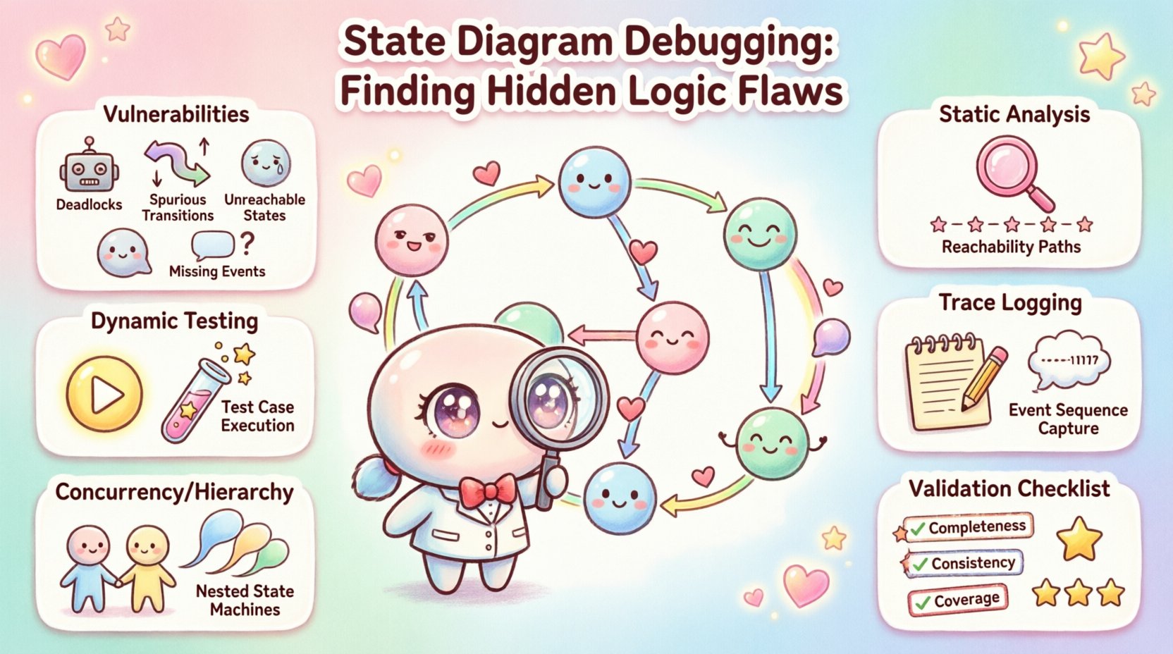
🧩 Understanding State Machine Vulnerabilities
State diagrams are visual representations of system behavior. While they offer clarity, they also introduce specific failure modes that are distinct from procedural code errors. These vulnerabilities often stem from the topology of the graph rather than the implementation of the event handlers.
When debugging, you must look for structural integrity issues first. A state machine that cannot reach a terminal state or gets stuck in a loop without progress is fundamentally broken. Below are the primary categories of logic flaws found in state diagrams.
- Deadlocks: A state where no outgoing transitions exist for the current event, halting the system.
- Spurious Transitions: Events that trigger unintended paths due to ambiguous target states.
- Unreachable States: States that cannot be entered from the initial state, rendering them useless.
- Redundant States: Multiple states performing identical functions, complicating maintenance.
- Missing Events: Scenarios where the system lacks a handler for a specific input in a given state.
- History State Errors: Logic errors involving shallow or deep history states that restore incorrect context.
Identifying these issues early prevents costly refactoring later. The debugging process involves both static review of the model and dynamic testing of the execution paths.
🛠️ Static Analysis Approaches
Static analysis involves examining the diagram without executing the underlying logic. This phase is crucial for catching topology errors before any code is generated or written. The goal is to verify the mathematical properties of the state graph.
1. Reachability Analysis
Every state in a well-formed diagram should be reachable from the start node. To debug this, trace a path from the initial state to every other state. If a state cannot be reached, it is a design artifact that serves no purpose.
- Start at the Initial State.
- Follow all possible transition arrows.
- Mark every state visited.
- Compare the marked states against the total state count.
- Any unmarked state is unreachable.
Unreachable states often occur when a sub-state is nested within a composite state that is never entered. In debugging scenarios, removing these states reduces cognitive load for future maintainers.
2. Transition Completeness
Every state should define behavior for expected events. If an event occurs in a state where no transition is defined, the system behavior is undefined. This is a common source of runtime crashes or silent failures.
When reviewing the diagram, look for:
- Default Transitions: Does the state handle unexpected inputs gracefully?
- Event Coverage: Are all documented API calls or user actions mapped to transitions?
- Guard Conditions: Are there guards that prevent all transitions from firing simultaneously, creating a deadlock?
A robust state machine handles the “what if” scenarios. If a transition guard evaluates to false, where does the flow go? If there is no fallback, the system stalls.
3. Cycle Detection
Infinite loops within a state machine can consume resources or freeze the processor. While some loops are intentional (e.g., waiting for input), others are accidental.
- Trace paths that return to the same state without consuming time or events.
- Identify loops that rely solely on guard conditions that never change.
- Ensure that loops have a mechanism to exit, such as a timeout or external signal.
🧪 Dynamic Testing and Execution Paths
Static analysis is powerful, but it cannot simulate the timing and state of the runtime environment. Dynamic testing involves feeding events into the system and observing the actual state changes. This is where hidden logic flaws often reveal themselves.
1. Path Coverage Testing
The objective is to execute every possible transition at least once. This requires designing test cases that force the system through specific states.
- Map the test cases to the transitions in the diagram.
- Ensure you test the negative path (where a transition should not happen).
- Verify that the system remains in the correct state after the event.
- Record the state ID after every event to confirm the diagram matches reality.
2. Stress Testing State Transitions
Fast, rapid-fire events can expose race conditions. If two events arrive in quick succession, does the state machine process them in the correct order? Does the state update atomically?
- Send high-frequency events to the state handler.
- Observe if the system skips states or processes them out of order.
- Check if intermediate states are visible or if the system jumps directly to the final state.
3. Boundary Condition Testing
Edge cases often hide logic flaws. What happens when a state machine is in its final state and receives an input? What happens if a transition is triggered immediately after a state entry?
- Test the Entry Action vs. the Exit Action timing.
- Verify behavior when transitioning from the initial state directly to a complex sub-state.
- Check behavior when a history state is invoked multiple times.
🔎 Trace Logging and Event Correlation
When a bug occurs in production, the state diagram is your map. To find the flaw, you need a trail. Implementing a robust logging mechanism is essential for debugging state machines.
1. State Entry and Exit Logging
Every time the system enters or leaves a state, it should record this event. This provides a timeline of execution.
- Log the Source State.
- Log the Target State.
- Log the Triggering Event.
- Log the Timestamp and Context Data.
This data allows you to reconstruct the path the system took leading up to the error.
2. Guard Condition Evaluation
Transitions often depend on guards (boolean conditions). If a transition fails, was it because the guard was false, or because the event was unknown?
- Log the evaluation result of every guard condition.
- Record the variables used in the guard.
- Identify if a guard condition is too restrictive.
Without this visibility, it is difficult to distinguish between a logic error in the state machine and a logic error in the data driving the guard.
⚡ Handling Concurrency and Hierarchy
Advanced state diagrams use orthogonal regions (concurrency) and nested states (hierarchy). These features add power but also significant complexity. Debugging these structures requires a deeper understanding of state composition.
1. Orthogonal Regions
Concurrent regions run independently. A flaw in one region might not immediately affect the other, leading to inconsistent overall system states.
- Verify that events in one region do not inadvertently modify variables used by another.
- Check for synchronization points where regions must align.
- Ensure that the system state is a valid combination of all region states.
2. Nested States and Inheritance
Nested states inherit behavior from their parent. However, this inheritance can mask specific logic errors.
- Does the child state override the parent’s exit action correctly?
- Are events handled at the parent level or the child level?
- When exiting a child, does the parent’s exit action fire?
3. History States
History states allow a composite state to remember its last sub-state. This is often a source of confusion.
- Deep History: Returns to the deepest active sub-state.
- Shallow History: Returns to the last active state at the immediate level.
- Ensure the history token is updated correctly upon entry.
- Debug scenarios where the history state is invoked before the composite state is fully initialized.
✅ Validation Checklist
To ensure your state machine is robust, run through this validation checklist. It covers the critical areas identified in this guide.
| Category | Check Item | Priority |
|---|---|---|
| Topology | Are all states reachable from the initial state? | High |
| Topology | Are there any deadlocks (states with no exit)? | High |
| Logic | Do all events have a defined handler or default transition? | High |
| Logic | Are guard conditions mutually exclusive where necessary? | Medium |
| Concurrency | Do orthogonal regions share mutable state safely? | Medium |
| History | Is the history state correctly initialized on first entry? | Medium |
| Testing | Has every transition been executed in a test case? | High |
| Logging | Is state entry/exit logged for troubleshooting? | Medium |
🧠 Common Scenarios and Fixes
Below are specific scenarios often encountered during debugging and the recommended strategies to resolve them.
Scenario 1: The System Freezes
If the application stops responding, the state machine is likely in a deadlock state. This happens when an event is received, but no transition matches the event in the current state.
- Diagnosis: Check the logs for the last state entered.
- Fix: Add a default transition or a catch-all handler to the problematic state.
- Prevention: Enforce a rule that every state must have an explicit “else” path.
Scenario 2: The System Jumps States
The system appears to skip a state or enter a state it shouldn’t. This is often due to spurious transitions or incorrect guard logic.
- Diagnosis: Compare the actual event sequence against the diagram.
- Fix: Tighten guard conditions or remove ambiguous transitions.
- Prevention: Use clear naming conventions for events to avoid collisions.
Scenario 3: Inconsistent State Restoration
After leaving and re-entering a composite state, the system does not remember where it was. This points to a history state implementation error.
- Diagnosis: Trace the path of the history token.
- Fix: Verify the history state points to the correct last active sub-state.
- Prevention: Document the history behavior clearly in the design phase.
🔄 Iterative Refinement
State machine design is rarely perfect on the first pass. Debugging is part of the design process. As you identify flaws, you refine the diagram. This iterative cycle ensures the final model is resilient.
When you find a flaw, do not just patch the code. Update the diagram. If the code differs from the diagram, the diagram is the source of truth. This alignment is critical for long-term maintainability.
📝 Summary of Best Practices
- Keep it Simple: Avoid overly complex hierarchies that obscure logic.
- Document Guards: Explain why a transition condition exists in the comments.
- Test Edge Cases: Focus on the boundaries of your state space.
- Visualize Paths: Use drawing tools to trace paths manually before coding.
- Monitor Production: Set up alerts for state anomalies in live environments.
By applying these strategies, you can significantly reduce the risk of hidden logic flaws. A well-debugged state machine is a reliable foundation for complex system behavior. It transforms potential chaos into predictable, controlled execution.