


In the field of computer science, modeling system behavior is as critical as writing the code itself. One of the most powerful tools for visualizing how a system reacts to inputs over time is the state diagram. These diagrams are essential for designing robust software, understanding protocol interactions, and defining user interface flows. This guide provides a deep dive into state machines, their graphical representations, and the methodologies used to construct them effectively.
Whether you are designing a network protocol, a game character AI, or a simple vending machine logic, understanding the lifecycle of an object through various conditions is vital. We will explore the components, types, construction methods, and common pitfalls associated with state diagrams.
What is a State Machine? 🔍
A state machine, formally known as a finite state machine (FSM) in many contexts, is a mathematical model of computation. It describes an object that can be in one of a finite number of states at any given time. The machine transitions from one state to another in response to some external stimuli, such as a user input or a system event.
Key characteristics include:
- Finite Set of States: The system cannot be in an infinite number of configurations simultaneously.
- Events: Triggers that cause the machine to move from one state to another.
- Transitions: The directed path taken between states when an event occurs.
- Initial State: The starting point of the machine’s execution.
- Final States: The ending points where the process terminates.
State diagrams are the visual notation used to represent these machines. They provide a clear map of the system’s logic, making it easier for developers to identify logic errors before implementation begins.
Core Components of a State Diagram 🧩
To draw a valid state diagram, one must understand the fundamental building blocks. Each element serves a specific purpose in defining the behavior of the system.
1. States
A state represents a condition or status during the life of the object. It defines what the system is doing at a particular moment. States are typically depicted as rounded rectangles.
- Simple State: A state that cannot be decomposed further.
- Composite State: A state that contains nested sub-states, allowing for hierarchical modeling.
- Entry/Exit Actions: Specific operations that occur when entering or leaving a state.
2. Transitions
Transitions are the arrows connecting states. They indicate the direction of flow. A transition is triggered by an event.
- Trigger: The event that initiates the transition (e.g., button press, timer expiration).
- Guard Condition: A boolean expression that must be true for the transition to occur. If the guard is false, the transition is ignored.
- Action: An operation performed during the transition (e.g., incrementing a counter).
3. Events and Signals
Events are occurrences that trigger state changes. They can be:
- Synchronous: Caused by an explicit request.
- Asynchronous: Caused by external factors like hardware interrupts.
Types of State Machines ⚙️
Not all state machines are created equal. Different scenarios require different models. Understanding the distinctions helps in selecting the right approach for your specific problem.
| Type | Description | Use Case |
|---|---|---|
| Mealy Machine | Outputs depend on both the current state and the input event. | Efficient for systems where output timing is critical relative to input. |
| Moore Machine | Outputs depend solely on the current state. | Systems requiring stable outputs regardless of transient input noise. |
| Deterministic FSM | For a given state and input, there is exactly one next state. | Most software logic and protocol definitions. |
| Non-Deterministic FSM | Multiple possible next states for the same input. | Theoretical models and specific parsing algorithms. |
Constructing a State Diagram: Step-by-Step 🛠️
Creating a state diagram is not just about drawing boxes and arrows. It requires a systematic approach to requirements analysis.
Step 1: Identify the System Boundaries
Define what is inside the system and what is outside. Identify the scope of the state machine. Is it the entire application, a specific module, or a single object?
Step 2: List Potential States
Brainstorm all possible conditions the system can be in. Avoid vague states like “Processing” unless the duration is significant. Be specific, such as “Calculating Tax” or “Waiting for Input”.
Step 3: Define Events and Triggers
What causes the system to change? List all user actions, system signals, and timeouts that affect the state.
Step 4: Map Transitions
Connect the states using arrows. Ensure every state has a path to every other state if the system is designed to be fully connected. Mark the initial state with a filled circle and final states with a double circle.
Step 5: Add Actions and Guards
Annotate the transitions with the logic required. Specify guard conditions where the transition is conditional. Define what happens inside the state (do actions) versus what happens during the transition (transition actions).
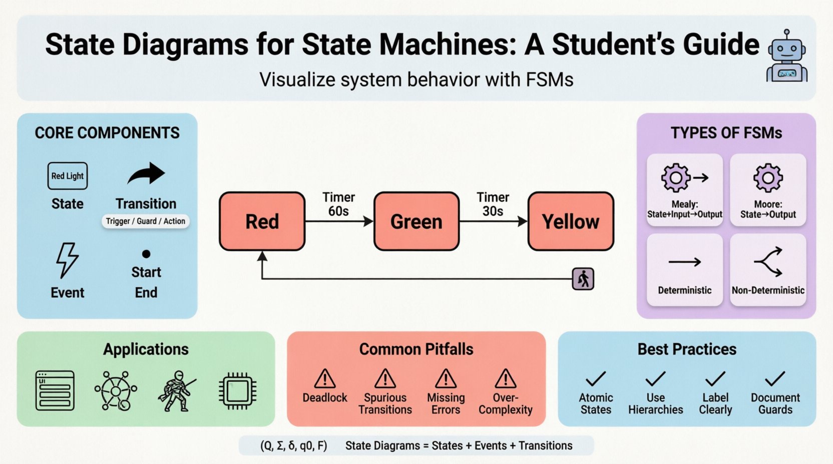
Example: Traffic Light Controller 🚦
To illustrate these concepts, let us walk through a classic example: a traffic light system. This system manages the flow of vehicles at an intersection.
System Requirements
- The light must cycle between Red, Yellow, and Green.
- A pedestrian button can request a change.
- Timers control the duration of each color.
State Definitions
- Idle: The system is off or resetting.
- Red: Traffic is stopped.
- Green: Traffic is flowing.
- Yellow: Warning phase before turning red.
Transition Logic
- Start ➔ Red: Upon initialization, the system starts in the Red state.
- Red ➔ Green: After a fixed timer (e.g., 60 seconds), transition to Green.
- Green ➔ Yellow: After a fixed timer (e.g., 30 seconds), transition to Yellow.
- Yellow ➔ Red: After a short timer (e.g., 5 seconds), transition back to Red.
- Emergency Event ➔ Red: Regardless of current state, an emergency signal forces the system to Red.
State Transition Tables 📊
While diagrams are visual, tables are often more practical for implementation. A state transition table maps the current state and input event to the next state and output action. This format is easier to translate directly into code.
| Current State | Event | Guard Condition | Next State | Action |
|---|---|---|---|---|
| Red | Timer Expired | True | Green | Turn On Green Light |
| Green | Timer Expired | True | Yellow | Turn On Yellow Light |
| Yellow | Timer Expired | True | Red | Turn On Red Light |
| Any | Emergency Signal | True | Red | Reset All Timers |
Common Pitfalls and Anti-Patterns ⚠️
Designing state machines is straightforward in theory but difficult in practice. Several common errors can lead to unpredictable behavior in production systems.
1. Deadlocks
A deadlock occurs when the system enters a state where no transitions are possible, yet the process has not terminated. This often happens if a required event never arrives. Always ensure every state has an outgoing transition or a defined error handler.
2. Spurious Transitions
Adding too many transitions makes the diagram unreadable. If a state has a transition for every possible event to every other state, the logic becomes spaghetti. Use default transitions or guard conditions to simplify.
3. Missing Error Handling
What happens if the input is invalid? A robust state machine must handle unexpected events gracefully, often by staying in the current state or moving to an error state.
4. Over-Complexity
Do not try to model everything in one machine. If a state diagram becomes too large (more than 20 states), consider splitting it into sub-machines or using hierarchical state machines.
Applications in Software Engineering 💻
State diagrams are not limited to theoretical exercises. They are widely used in modern software development.
1. User Interface (UI) Flow
Web applications and mobile apps often follow state-based logic. For example, a form submission might have states like Idle, Validating, Sending, Success, or Error. Managing these states prevents users from submitting duplicate requests.
2. Network Protocols
Protocols like TCP rely heavily on state machines. The connection lifecycle (SYN, ESTABLISHED, CLOSE_WAIT, etc.) is a classic state machine implementation. Understanding this helps in debugging network issues.
3. Game Development
Character AI often uses state machines to determine behavior. A character might transition between Idle, Chasing, Attacking, and Fleeing based on player proximity and health.
4. Embedded Systems
Microcontrollers often run state machines to manage hardware resources. A sensor reading loop might transition between Calibrating, Reading, and Transmitting states.
Best Practices for Design 📝
To create maintainable and clear state diagrams, adhere to these guidelines.
- Keep States Atomic: Each state should represent a single, coherent behavior. Avoid states that bundle unrelated actions.
- Use Hierarchical States: If a group of states shares common transitions, group them into a composite state to reduce visual clutter.
- Label Clearly: Name states and transitions descriptively. Avoid abbreviations that might confuse future maintainers.
- Document Guards: Clearly document the logic behind guard conditions. A transition without a guard is unconditional, which is rare.
- Review Regularly: As requirements change, the state machine must evolve. Regular reviews ensure the diagram matches the actual code.
Theoretical Underpinnings 📐
For computer science students, understanding the mathematical basis is beneficial. A finite state machine can be defined as a 5-tuple (Q, Σ, δ, q0, F), where:
- Q: A finite set of states.
- Σ: A finite set of input symbols (alphabet).
- δ: The transition function (Q × Σ → Q).
- q0: The initial state.
- F: The set of final states.
This formalism allows for the verification of system properties, such as reachability (can a state be reached?) and safety (will an invalid state ever be entered?).
Differentiating State Diagrams from Flowcharts 🔄
It is common to confuse state diagrams with flowcharts. While they both use arrows, they serve different purposes.
| Feature | State Diagram | Flowchart |
|---|---|---|
| Focus | Focuses on the state of the object. | Focuses on the flow of control. |
| Looping | States persist over time. | Process steps are sequential. |
| Concurrency | Can model concurrent states (orthogonal regions). | Typically sequential. |
| Input Driven | Driven by external events. | Driven by logic conditions. |
Conclusion 🏁
State diagrams provide a structured way to think about system behavior. By breaking down complex logic into discrete states and transitions, developers can build more reliable and predictable software. Whether you are a student learning the fundamentals or a professional designing complex systems, mastering this notation is a valuable skill. Remember to keep your models simple, document your logic, and always test your state transitions against real-world scenarios.
As you continue your studies, practice drawing diagrams for various systems. The more you model, the more intuitive the patterns become. This foundational knowledge will serve you well in architecture design, debugging, and system optimization.