


Data Flow Diagrams (DFDs) serve as the blueprint for information systems. They map the movement of data between processes, data stores, external entities, and the data itself. A well-constructed diagram does more than just show where data goes; it reveals the logic, integrity, and security of the system architecture. This article examines three distinct scenarios to illustrate how rigorous modeling leads to stable, maintainable systems.
🗺️ Understanding the Core Components
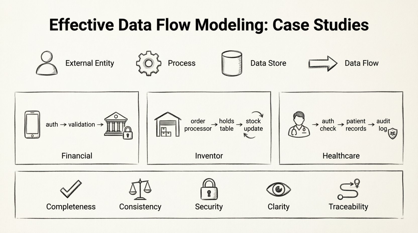
Before diving into specific implementations, it is essential to define the standard elements involved in any data flow model. These components remain consistent regardless of the industry or complexity of the system.
- External Entities: Sources or destinations of data outside the system boundary. These could be users, other systems, or regulatory bodies.
- Processes: Transformations that convert input data into output data. Every process must have at least one input and one output.
- Data Stores: Locations where data is held for later use. This includes databases, file systems, or physical archives.
- Data Flows: The arrows connecting the components, indicating the direction and content of data movement.
Accuracy in representing these elements is critical. Mislabeling a data store as a process, for example, can lead to confusion regarding where data is persisted versus where it is transformed.
🏦 Case Study 1: Financial Transaction Processing
The financial sector demands high precision regarding data integrity and security. In this scenario, we examine a system designed to process payment requests from a mobile application to a banking core.
🔍 System Context
The primary goal is to ensure that money moves only when specific conditions are met. The system must validate funds, verify user identity, and record the transaction for audit purposes.
🔄 Data Flow Breakdown
The modeling process began with a Level 0 diagram, providing a high-level view of the system. This revealed three main processes: Authentication, Validation, and Posting.
- Authentication: When a user initiates a transfer, their credentials are sent to the security service. The system checks the user’s status against the Active Users data store.
- Validation: Once authenticated, the request moves to the validation process. Here, the system checks the Account Balances store to ensure sufficient funds. It also verifies the Transaction Limits table.
- Posting: If validation passes, the transaction is recorded in the Transaction Log data store. The Account Balances are updated, and a confirmation signal is sent back to the user.
A critical decision in this model was the separation of the Validation and Posting processes. Merging them would create a single point of failure. By keeping them distinct, the system can roll back the validation state without corrupting the permanent log if a network interruption occurs.
📊 Component Mapping
| Component | Type | Role in System |
|---|---|---|
| Mobile App | External Entity | Initiates request and receives confirmation. |
| Security Service | Process | Verifies credentials against stored hash. |
| Account Balances | Data Store | Reads current funds and writes new totals. |
| Transaction Log | Data Store | Immutable record of all movements. |
📦 Case Study 2: Inventory Management System
Inventory systems require synchronization across multiple locations. The challenge here is not just moving data, but ensuring that the representation of physical stock matches the digital record in real-time.
🔍 System Context
This system connects a warehouse management terminal with an online sales portal. Data flows bidirectionally: sales reduce stock, and incoming shipments increase it. The model must handle concurrency to prevent overselling.
🔄 Data Flow Breakdown
The Level 1 diagram revealed a complex web of interactions involving the Order Processor and the Stock Controller.
When an order is placed:
- The Order Processor checks the Inventory Database.
- If stock is available, a Reservation Token is created and stored in a temporary Holds Table.
- The order is confirmed to the customer.
- A separate process, Stock Reconciliation, runs periodically to clear expired reservations and update the Inventory Database.
This approach prevents the system from locking the entire database for every click. The use of a temporary Holds Table allows the system to manage contention without blocking other users from viewing inventory levels.
📊 Concurrency Handling
| Scenario | Data Flow Action | Outcome |
|---|---|---|
| Single User | Check Stock → Reserve → Confirm | Success |
| Two Users (Same Item) | User A reserves → User B checks (Stock Low) | User B sees updated count |
| Reservation Timeout | Holds Table → Cleanup Process | Stock returned to pool |
The model highlights the importance of the Cleanup Process. Without this, the Holds Table would grow indefinitely, consuming memory and slowing down queries.
🏥 Case Study 3: Healthcare Patient Records
Healthcare data modeling prioritizes privacy and access control. The flow of information must be strictly regulated based on the role of the user and the sensitivity of the data.
🔍 System Context
This system manages patient history for a network of clinics. Data includes personal identification, medical history, and lab results. The model must ensure that only authorized personnel can view specific records.
🔄 Data Flow Breakdown
The DFD for this system introduces the concept of Access Control as a distinct process layer. Data does not flow directly from the patient record to the doctor’s screen.
- Request: The doctor selects a patient ID.
- Authorization: The system checks the User Permissions store to see if the doctor has access to that specific clinic’s data.
- Retrieval: If authorized, the Query Engine fetches data from the Patient Records store.
- Logging: A record of the access event is written to the Audit Log before the data is displayed.
This separation ensures that even if the data store is compromised, the access logs provide a trail of who requested what data. The Audit Log is a critical data store in this model, often treated with higher security clearance than the medical records themselves.
📊 Privacy Levels
| Role | Data Access | Data Flow Path |
|---|---|---|
| Receptionist | Schedule Only | Schedule Store → Display |
| Nurse | Vitals & Meds | Medical Store → Auth Check → Display |
| Specialist | Full History | Medical Store → Auth Check → Display |
The diagram clearly distinguishes between the Receptionist and the Specialist paths. Even though they both access a patient, the data streams are filtered differently. This granularity is essential for compliance with data protection regulations.
🛠️ Methodology for Effective Modeling
Successful modeling requires a disciplined approach. It is not merely about drawing boxes and arrows; it is about understanding the business logic and translating it into a technical representation.
1. Define the Scope Clearly
Start by determining the boundary of the system. What is internal, and what is external? In the financial case study, the banking core was an external entity to the mobile app layer. Clarifying this prevents scope creep during development.
2. Decompose Gradually
Begin with a high-level context diagram. Then, expand each process into a Level 1 diagram. Continue decomposing until the processes are simple enough to be coded directly. This hierarchical approach keeps the model readable.
3. Validate Data Stores
Every data store must have a clear purpose. Ask: Why is this data saved? Is it needed for a future process? If a data store has no incoming or outgoing flows, it is dead weight. In the inventory case, the Holds Table was justified by the need for concurrency control.
4. Review for Consistency
Ensure that data entering a process matches the data expected by the next process. Mismatched formats or missing fields are common sources of system errors. Consistency checks should be documented within the data flow labels.
🔄 Maintenance and Evolution
Systems evolve, and the data flow models must evolve with them. A static diagram becomes obsolete as soon as the business requirements change.
When introducing a new feature, map the new data flows against the existing diagram. Look for conflicts. For instance, adding a notification feature to the financial system might require a new process to handle email delivery and a new data store for message templates.
Regular audits of the DFD are recommended. Compare the actual system logs against the planned data flows. Discrepancies indicate either a deviation in implementation or an outdated model. Updating the model ensures that new developers can understand the architecture without reverse-engineering the code.
📋 Summary of Key Considerations
The following checklist ensures that data flow models remain effective and accurate throughout the lifecycle of the project.
- Completeness: Does every process have inputs and outputs?
- Consistency: Do data flows match in format and type across processes?
- Security: Are sensitive data flows protected by authorization processes?
- Clarity: Are labels descriptive and unambiguous?
- Traceability: Can every piece of data be traced back to its source and destination?
By adhering to these principles, organizations can build systems that are robust, secure, and easy to maintain. The effort invested in detailed modeling pays dividends during the testing and deployment phases, reducing the likelihood of critical failures.
Data flow modeling is a foundational skill for system architects. It bridges the gap between abstract requirements and concrete implementation. Whether managing financial transactions, inventory levels, or patient records, the logic remains the same: data must be captured, transformed, stored, and retrieved with precision. Following the patterns established in these case studies provides a reliable framework for designing complex information systems.
🚀 Final Thoughts on Architecture
The quality of a system is often determined before a single line of code is written. The diagrams created during the planning phase dictate the performance and reliability of the final product. By focusing on the movement of data rather than just the storage, architects can identify bottlenecks and security gaps early.
Remember that a model is a communication tool as much as it is a technical specification. It allows stakeholders to visualize the system’s behavior. When the diagram is clear, the code follows naturally. When the diagram is vague, the code becomes a maintenance nightmare.
Apply these principles to your next project. Start with the context, break down the processes, and verify the data stores. A disciplined approach to data flow modeling is the hallmark of a mature engineering practice.