
Mastering UML Sequence Diagrams for Microservices with AI
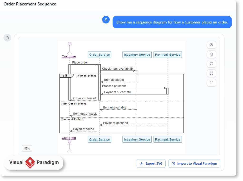
In modern software engineering, understanding the flow of data between different system components is critical. The image above illustrates a classic Sequence Diagram for an “Order Placement” scenario, generated directly through a conversational interface using Visual Paradigm’s AI capabilities. This tutorial will guide you through the architectural concepts depicted in the diagram, the specific modeling syntax used (such as alt fragments), and how to leverage AI tools to automate this documentation process.
Understanding the System Architecture
The diagram models a distributed system where a central user request triggers interactions across multiple backend services. This is a common pattern in microservices architectures. The key components (or “Lifelines”) involved in this interaction are:
- Customer: Represented by the UML Actor symbol, this is the external entity initiating the request.
- Order Service: The entry point or “Facade” that coordinates the order logic. It receives the request and delegates tasks to other services.
- Inventory Service: Responsible for checking if the requested goods are available.
- Payment Service: Handles the financial transaction and validates funds.
The diagram visualizes the temporal ordering of these interactions. Notice the vertical dashed lines extending downwards from each component; these are lifelines, representing the existence of the object over time. The horizontal arrows represent method calls or messages passed between these services.
Modeling Logic: The “alt” Fragment
Real-world software is rarely a straight line from start to finish; it involves decision-making. The diagram demonstrates this using an Alt (Alternative) Fragment, denoted by the large rectangular frame labeled alt in the top left corner. This structure allows you to model conditional logic, similar to an if-else statement in programming.
In this specific scenario, the logic flows as follows:
- Initial Request: The Customer places an order, triggering the Order Service.
- Inventory Check: The system must first verify stock. This is an external call to the Inventory Service.
- Condition 1 [Item in Stock]: If the inventory check returns “Item available,” the system proceeds to the Payment Service to process the transaction.
- Condition 2 [Item Out of Stock]: If the inventory check returns “Item unavailable,” the system stops and returns an error message to the Customer.
- Condition 3 [Payment Failed]: Even if stock is available, the diagram accounts for a failure in the Payment Service, returning a “Payment declined” message.
Generating Diagrams with AI
Creating these diagrams manually can be time-consuming. Visual Paradigm’s AI Chatbot allows you to generate this architecture instantly using natural language. By describing your system’s actors and the logic flow (e.g., “Check stock, then process payment, handle errors”), the AI renders the sequence diagram immediately.
Once generated, the diagram is fully editable. You can import it back into Visual Paradigm for further refinement, export it as SVG for documentation, or even extract the underlying code to use in other tools.
Tooling: Visual Paradigm
Visual Paradigm is a comprehensive modeling platform that supports various UML diagrams. Its AI integration simplifies the transition from abstract ideas to concrete architectural models, making it an essential tool for system architects and developers.