Data Flow Diagrams serve as the backbone of system analysis and design. They map out how information moves through a system, highlighting processes, data stores, and external interactions. A well-constructed DFD clarifies complex logic for developers and stakeholders alike. However, creating an accurate diagram requires discipline. Many analysts fall into specific traps that compromise the integrity of the model.
Understanding these pitfalls is essential for maintaining system reliability. This guide details seven frequent errors and how to correct them effectively. We will explore the theoretical implications of each mistake and provide practical guidance for improvement.
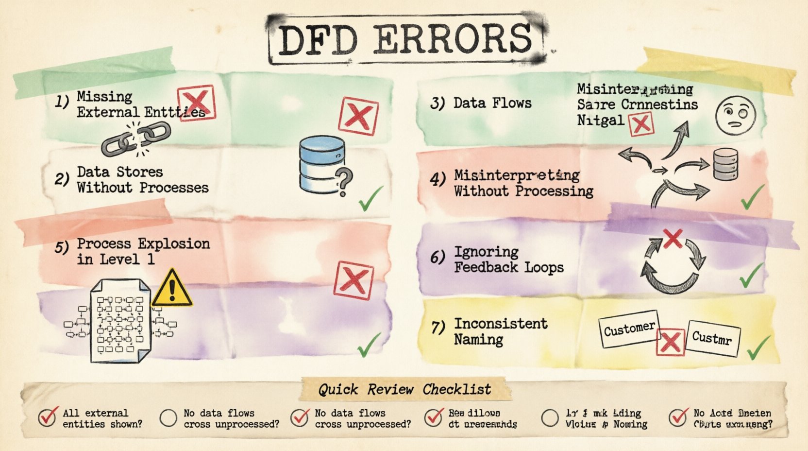
1. Missing External Entities 🚫
One of the most fundamental errors involves omitting external entities. External entities represent sources or destinations of data outside the system boundary. These could be users, other systems, or organizations. When a DFD fails to show where data originates or where it ultimately lands, the diagram becomes incomplete.
Consider a transaction processing system. If the diagram shows the calculation of tax but does not show the customer submitting the order, the flow is broken. Similarly, if the system sends a confirmation email, the email server must be represented as an external entity or at least the action must be linked to a clear output. Without these boundaries, the scope of the system remains ambiguous.
- Impact: Developers may build processes that expect data that never arrives.
- Correction: Identify every actor or system interacting with the software.
- Visual Cue: Use rectangles to denote entities clearly.
Always verify that every data flow has a start and an end point. A line in a diagram cannot simply terminate in empty space. It must connect to a process, a data store, or an external entity.
2. Data Stores Without Processes 🗄️
Data stores represent permanent storage. They hold information for later retrieval. A critical mistake occurs when a data store exists without any processes reading from or writing to it. This creates a “black hole” or an unreachable archive within the model.
If a database table is defined in the diagram but no process is shown updating it, that storage is logically disconnected. Conversely, if a process writes to a store but nothing ever reads from it, the data serves no purpose. This often happens when analysts focus on the user interface and forget the backend persistence layer.
To fix this, trace every data store. Ensure there is at least one incoming flow and one outgoing flow. This ensures the data is both created and utilized. It validates the lifecycle of the information within the system architecture.
3. Data Flows Crossing Without Processing 🔄
Data flows should only connect to processes. A common error is drawing a line from one data store directly to another, or from an external entity directly to another entity, bypassing the processing logic.
In a valid DFD, data must be transformed. When data moves from a source to a destination, something must act upon it. A process represents this transformation. If data flows directly between two stores, it implies automatic synchronization without logic, which is rarely accurate in complex systems.
| Incorrect Flow |
Correct Flow |
| Entity → Data Store |
Entity → Process → Data Store |
| Data Store → Data Store |
Data Store → Process → Data Store |
| Entity → Entity |
Entity → Process → Entity |
Ensuring every arrow passes through a process box maintains the logical integrity of the model. It forces the analyst to define what happens to the data during transit.
4. Misinterpreting Data Store Connections 📉
Another nuance involves the direction of data flow relative to data stores. A process can write to a store and read from it. However, analysts often confuse the direction of the arrow. The arrow should point towards the store when data is written and away from the store when data is read.
Reversing these arrows creates confusion about the state of the system. Does the process store the result, or does it retrieve the result? Clear notation is vital. Some methodologies require distinct notations for read and write operations, but consistency is the key requirement regardless of the specific standard used.
Review every connection to a data store. Label the flow if necessary to clarify the operation. For example, “Update Record” or “Fetch Balance”. This reduces ambiguity during the development phase.
5. Process Explosion in Level 1 Diagrams 🧩
DFDs are hierarchical. A Context Diagram shows the system as a single process. Level 0 breaks this down into major sub-processes. Level 1 further decomposes those sub-processes. A frequent error is putting too much detail into Level 1.
When a Level 1 diagram becomes cluttered with dozens of tiny processes, it loses its value as a high-level map. It becomes a flowchart rather than a data flow diagram. The purpose of Level 1 is to show the major functional modules, not every individual calculation.
If a process box contains more than five to seven sub-processes, it should be exploded into a separate diagram. This keeps the visual hierarchy clean. It allows the viewer to understand the system’s structure without getting lost in the weeds.
- Rule of Thumb: If you can draw the diagram on a single standard page without scrolling, it is likely appropriate.
- Goal: Balance detail with readability.
6. Ignoring Feedback Loops and Control Data 🔄
Systems are rarely linear. They often require feedback to adjust behavior. A common oversight is failing to diagram control flows or feedback loops. For instance, a user might receive an error message and re-enter data. This loop must be visible.
If the diagram shows a straight line from input to output, it implies a one-way trip. Real systems involve validation, rejection, and re-processing. Ignoring these loops leads to systems that crash or behave unpredictably when errors occur.
Include the path where data is returned for correction. Show the process that validates the input. Show the process that handles the exception. This creates a robust model that accounts for real-world usage scenarios.
7. Inconsistent Naming Conventions 📝
Clarity depends on consistent language. Using “User” in one part of the diagram and “Customer” in another confuses the reader. Similarly, a process named “Get Data” next to a process named “Retrieve Information” suggests they might do different things.
Standardize your terminology. Create a glossary for the project and stick to it. Data flows should be named with a noun (e.g., “Order Details”), while processes should be named with a verb-noun combination (e.g., “Calculate Total”).
Consistency aids in communication. When developers read the diagram, they should not have to guess what a term means. It reduces the risk of misinterpretation and rework later in the development cycle.
Impact of Errors on System Design 📊
Why does this level of precision matter? Errors in DFDs ripple through the entire software development lifecycle. A missing entity might result in a missing API endpoint. A broken data flow could lead to a null pointer exception in production.
Furthermore, maintenance becomes difficult. If the documentation does not match the code, future engineers will spend more time guessing than building. Correcting a DFD mistake early is significantly cheaper than fixing a deployed bug.
Review Checklist ✅
Before finalizing your diagram, run through this verification list:
- Are all external entities defined and labeled?
- Does every data store have read and write access?
- Do all data flows pass through a process?
- Are arrow directions correct for data stores?
- Is the Level 1 diagram not too complex?
- Are feedback loops and error paths included?
- Are names consistent throughout the document?
Adhering to these principles ensures your Data Flow Diagrams are accurate, reliable, and useful tools for system architecture. Take the time to review your work against these common pitfalls.