


Data Flow Diagrams, often abbreviated as DFDs, serve as a foundational tool in systems analysis and design. They provide a visual representation of how information moves through a system. Unlike other diagrams that focus on control logic or hardware, DFDs prioritize the flow of data itself. This approach helps stakeholders understand the transformation of data from input to output without getting bogged down in implementation details.
Whether you are mapping out a new software architecture or analyzing an existing business process, a well-constructed DFD clarifies relationships between components. It acts as a blueprint for developers and a communication bridge for business owners. This guide explores the core principles, symbols, levels, and best practices required to create effective diagrams.
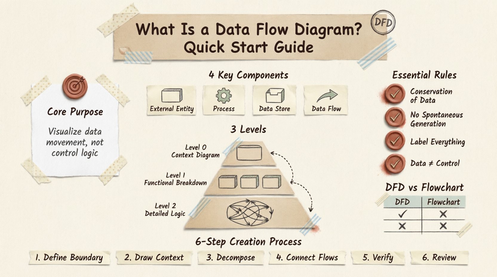
Understanding the Core Purpose 🎯
The primary function of a Data Flow Diagram is to visualize the movement of data. It does not show the sequence of operations or the timing of events. Instead, it answers the question: “Where does the data come from, where does it go, and how is it changed?” This distinction is crucial when separating logical design from physical implementation.
When building a system, teams often face the challenge of complexity. A DFD breaks this complexity down into manageable chunks. By isolating specific processes, you can analyze data integrity and ensure no information is lost or corrupted during transmission. It allows analysts to spot bottlenecks where data accumulates unnecessarily or flows where it is not needed.
DFDs are particularly valuable during the requirements gathering phase. They help verify that all necessary inputs and outputs are accounted for. If a process produces an output but has no defined source, the diagram reveals a gap in the design. Conversely, if data enters the system but is never used, it indicates redundancy.
Key Components of a DFD 🧩
Every Data Flow Diagram is built using a specific set of symbols. While notation can vary slightly between methodologies (such as Gane and Sarson or Yourdon and Coad), the fundamental elements remain consistent. Understanding these four core components is essential for accurate diagramming.
1. External Entities 🚪
External entities represent sources or destinations of data outside the system boundaries. These are the users, other systems, or organizations that interact with the process being modeled. They are often depicted as rectangles or squares.
Source: An entity that provides data to the system (e.g., a Customer placing an order).
Sink: An entity that receives data from the system (e.g., a Government Agency receiving tax reports).
It is important to remember that entities exist outside the scope of the current system. They are the boundary markers that define what the system controls and what it does not.
2. Processes ⚙️
Processes represent the activities that transform data. They are the “work” being done within the system. A process takes input data, performs an operation, and produces output data. In DFD notation, these are often shown as rounded rectangles or circles.
Each process must have a name that describes its function using a verb and an object. For example, “Calculate Interest” or “Update Inventory.” A process cannot exist without data flowing into it and out of it. If a circle has no incoming or outgoing lines, it serves no purpose in the diagram.
3. Data Stores 🗄️
Data stores are locations where information is held for later use. They represent databases, files, or physical archives. Unlike processes, data stores do not change the data; they simply retain it. These are typically depicted as open-ended rectangles or parallel lines.
When drawing a DFD, ensure that every data store has at least one incoming flow and one outgoing flow over time, unless it is a terminal storage point. This ensures the data is being accessed and updated, maintaining the integrity of the stored information.
4. Data Flows 🔄
Data flows are the arrows that connect the components. They show the direction in which data moves. Every arrow must have a label describing the content of the data packet. For instance, an arrow from a “Customer” to a “Process” might be labeled “Order Request,” while an arrow from a “Process” to a “Data Store” might be “Sales Record.”
Crucially, data flows must be consistent. If a process outputs “Customer Details,” the receiving process or store must be able to accept that specific data structure. You cannot have a flow of “Financial Data” entering a process designed to handle “Textual Input” without a transformation step.
Levels of Data Flow Diagrams 📉
A complete system is rarely represented in a single diagram. To manage complexity, DFDs are decomposed into levels. This hierarchical approach allows you to start with a high-level overview and drill down into specific details.
Level 0: The Context Diagram 🌍
The Level 0 diagram, often called the Context Diagram, provides the broadest view. It represents the entire system as a single process. All external entities are shown interacting with this central process.
This diagram establishes the system boundaries clearly. It answers the question: “What is the system, and who interacts with it?” It does not show internal processes or data stores. It focuses solely on the major inputs and outputs relative to the external world.
Level 1: The Functional Breakdown 🔍
Level 1 expands the single process from the Context Diagram into its major sub-processes. This is where the internal structure begins to emerge. You will see multiple processes, data stores, and the flows connecting them.
The inputs and outputs for the Level 1 diagram must match the Context Diagram. If the Context Diagram shows an input from “User,” the Level 1 diagram must still show that input entering the system, even if it enters a specific sub-process. This ensures data conservation across levels.
Level 2: Detailed Logic 🧠
Level 2 diagrams break down specific processes from Level 1 further. This level is used for complex operations that require detailed logic. Not every process needs a Level 2 diagram; only those that are sufficiently complex to warrant further decomposition.
At this stage, the focus shifts to the specific data transformations required. You might see multiple passes through data stores or complex branching logic represented through multiple flows. This level is often where developers begin to map the requirements to actual code structures.
Rules for Consistency and Accuracy ✅
Creating a valid DFD requires adherence to specific rules. Violating these rules leads to confusion and design errors. Below are the fundamental principles that govern DFD construction.
Conservation of Data
Data cannot be created or destroyed within a process. It must flow in and flow out. If a process outputs a “Report,” the necessary data to create that report must enter the process. If the data enters and disappears, the diagram is logically flawed.
No Spontaneous Generation
A process cannot exist without data entering it. You cannot have a process that simply “happens” without an input. Every action in a system is triggered by data or an event. Ensure every process has at least one incoming data flow.
Control vs. Data
DFDs do not show control flows, such as “if/else” logic or timing signals. While a process might make a decision, the DFD only shows the data resulting from that decision, not the decision mechanism itself. For control logic, other modeling techniques are more appropriate.
Labeling Standards
Every arrow must be labeled. An unlabeled arrow provides no information about the data content. Similarly, every process must be named with a verb-noun phrase. Ambiguity in labeling leads to misinterpretation during the development phase.
Differences Between DFDs and Flowcharts 🆚
It is common to confuse Data Flow Diagrams with Flowcharts. While both use arrows and shapes, they serve different purposes. Understanding the distinction prevents misuse in system documentation.
Feature | Data Flow Diagram (DFD) | Flowchart |
|---|---|---|
Focus | Movement of data and transformation | Sequence of steps and logic flow |
Control | Does not show control logic (loops, decisions) | Explicitly shows decisions and loops |
Time | Does not represent time or sequence | Often represents time or order of execution |
Components | Entities, Processes, Stores, Flows | Start/End, Process, Decision, Input/Output |
Use a Flowchart when you need to program the logic of an algorithm. Use a DFD when you need to document the system architecture and data requirements. They are complementary tools, not interchangeable ones.
Creating a Data Flow Diagram: Step-by-Step 🛠️
Follow this structured approach to build a reliable diagram for your project. This process ensures logical consistency from the start.
Define the System Boundary: Determine what is inside the system and what is outside. Identify the primary external entities that interact with it.
Draw the Context Diagram: Sketch the single process representing the system. Draw arrows for major inputs and outputs connecting to external entities.
Decompose the Process: Break the main process into sub-processes. Identify the data stores required to support these processes.
Connect Data Flows: Draw lines between entities, processes, and stores. Label every line with the specific data being transferred.
Verify Conservation: Check that inputs and outputs balance across levels. Ensure no data disappears or appears magically.
Review and Refine: Walk through the diagram with stakeholders. Ensure the visual representation matches their understanding of the business process.
Logical vs. Physical DFDs 🧠🖥️
DFDs can be categorized into two types based on their abstraction level. Understanding this distinction helps in communicating with different audiences.
Logical DFD: This diagram focuses on what the system does, not how it does it. It ignores hardware, software, or human roles. It describes the business requirements. For example, “Process Order” is a logical step, regardless of whether a human clerk or an automated script handles it.
Physical DFD: This diagram describes how the system is actually implemented. It includes specific hardware, software modules, and human actors. If the Logical DFD says “Process Order,” the Physical DFD might show “Web Server API calls Database to Check Stock.” Physical DFDs are typically used later in the development cycle when implementation details are finalized.
Common Challenges in DFD Design 🚫
Even experienced analysts encounter issues when modeling complex systems. Being aware of these challenges helps in producing cleaner diagrams.
Over-Crowding: Trying to fit too much detail into a single diagram makes it unreadable. Use decomposition to split complex areas into separate diagrams.
Missing Data Stores: Sometimes data is assumed to exist without being stored. Ensure every piece of information that needs to persist is linked to a data store.
Crossed Lines: While unavoidable in complex systems, try to minimize crossing lines. It reduces visual clarity. Use off-page connectors if the diagram spans multiple pages.
Incorrect Terminology: Using technical jargon in a diagram intended for business users causes confusion. Stick to the vocabulary of the domain being modeled.
Integrating DFDs with Other Models 📚
Data Flow Diagrams rarely exist in isolation. They are part of a larger ecosystem of system documentation. Integrating them with other models enhances their value.
Entity-Relationship Diagrams (ERD): While DFDs show how data moves, ERDs show how data is structured. The data stores in a DFD often correspond to tables in an ERD. Using both ensures data flow aligns with data structure.
Unified Modeling Language (UML): In modern object-oriented design, DFDs can be mapped to Use Case Diagrams or Activity Diagrams. While UML is more comprehensive, DFDs offer a clearer view of data persistence and transformation for specific subsystems.
The Value of Visual Clarity 🌟
Effective system design relies on clear communication. A Data Flow Diagram serves as a universal language between analysts, developers, and stakeholders. It removes ambiguity regarding data requirements and system boundaries.
By adhering to standard conventions and focusing on data movement rather than control logic, you create a document that stands the test of time. Even if the technology stack changes, the flow of data often remains constant. This makes the DFD a durable asset for future maintenance and scaling.
Start with the Context Diagram, decompose with care, and always verify data conservation. With practice, you will find that DFDs become an intuitive way to explore and document the architecture of any complex system.