1. Introduction
This case study explores the design and implementation of a UML State Machine Diagram to model the behavioral lifecycle of a modern smartphone operating system. The diagram captures the dynamic behavior of a smartphone from power-off to active usage, including states such as PowerOff, Standby, Booting, Running, Locked, Authenticated, Sleeping, and transitions triggered by user actions and system events.
The goal is to demonstrate how UML state machines can be used to model complex, real-world systems with hierarchical nesting, concurrent behavior, and event-driven transitions—making them ideal for embedded systems, mobile applications, and user interface design.
2. Problem Statement
Design a clear, maintainable, and scalable behavioral model for a smartphone’s operational lifecycle. The system must:
- Handle power-on/power-off sequences.
- Manage user authentication (PIN/password).
- Support multiple application modes (e.g., HomeScreen, Camera, Settings).
- Respond to user inputs (power button, touch, swipe).
- Enforce security via locking mechanisms.
- Reflect timing-based state changes (e.g., auto-lock, timeout).
Traditional flowcharts or activity diagrams fail to express hierarchical structure and state dependencies effectively. UML State Machine Diagrams provide a better solution.
3. Key Concepts in UML State Machine Diagrams
State Machine Diagram: Case Study

3.1. State
A state represents a condition or situation during the life of an object. In this case:
PowerOff,Running,Locked,Authenticated,Sleeping, etc., are states.- States define when certain behaviors are active or conditions are met.
Example:
Runningindicates the phone is active and usable.
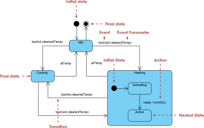
3.2. Transition
A transition is an arrow from one state to another, triggered by an event and optionally including:
- Guard condition (optional)
- Action (optional)
Example:
Standby --> Booting : power button
- Event:
power button- No guard condition (always allowed)
- Action: None
3.3. Initial Pseudostate ([*])
The [*] symbol denotes the initial state—the starting point of the state machine.
[*] --> PowerOffmeans the system starts in thePowerOffstate.
3.4. Final State
Although not explicitly shown here, a final state ([X]) would represent the end of the system’s lifecycle (e.g., after shutdown). In practice, PowerOff acts as the final state.
3.5. Composite States (Hierarchical Nesting)
A composite state contains substates and allows for hierarchical nesting. This is crucial for managing complexity.
Example:
state Running {
  [*] --> Locked
  state Locked {
    [*] --> ScreenLocked
    ScreenLocked --> Authenticated : correct PIN/password
  }
  state Authenticated {
    [*] --> HomeScreen
    '...
  }
}
Runningis a composite state with two substates:LockedandAuthenticated.Lockeditself containsScreenLocked.- This structure avoids redundancy and supports orthogonal regions (not shown here but applicable in advanced cases).
Benefit: Reduces complexity and improves readability.
3.6. Entry/Exit Actions
While not fully visible in this diagram, entry and exit actions can be defined:
entry / showBootAnimation()exit / stopBootAnimation()
These are useful for system-level actions during state changes.
3.7. Internal Transitions
An internal transition occurs within the same state and does not change the state. It’s used for actions without transition.
Example:
HomeScreen --> HomeScreen : swipe up → camera
→ This is actually a transition, but if the user swipes and the screen updates without changing state, it would be internal.
3.8. Superstate / Substate Relationships
Runningis the superstate ofLockedandAuthenticated.Lockedis the superstate ofScreenLocked.- This enables state hierarchy, where entry/exit actions propagate down the hierarchy.
3.9. Concurrent States (Optional Extension)
Although not used in this example, orthogonal regions allow multiple independent state machines to run in parallel.
Example:
- One region:
Runningstate- Another region:
BatteryLoworNetworkConnectedflags
→ Enables modeling of parallel behaviors.
3.10. Guards and Events
- Guard condition: A boolean expression that must be true for a transition to occur.
- Event: A signal or trigger (e.g.,
power button,touch,timeout).
Example:
Locked --> Sleeping : timeout / power button
→ This means: when timeout occurs, and the power button is pressed, transition happens.
Note: The
/denotes actions or conditions.
4. Guidelines for Effective UML State Machine Diagrams
✅ Best Practices
| Guideline | Application in This Diagram |
|---|---|
| Use composite states for complex behavior | Running contains Locked and Authenticated → avoids flat, sprawling diagrams. |
| Avoid overly deep nesting | Max 2–3 levels of hierarchy for readability. |
| Use meaningful state names | ScreenLocked, Authenticated, Sleeping clearly describe behavior. |
| Group related states under superstates | Locked and Authenticated under Running. |
| Use notes for clarity | Notes explain the purpose of Running and Authenticated states. |
| Prioritize transitions based on user flow | Power-on → Booting → Running → Locked → Authenticated → HomeScreen |
Use [*] for initial state |
Clear starting point. |
| Avoid cycles unless necessary | All transitions are logically sound; no infinite loops. |
❌ Common Pitfalls to Avoid
- Too many states: Can lead to unmaintainable diagrams. Use composite states.
- Missing guards on sensitive transitions: e.g.,
Authenticated --> Lockedshould have a guard likeif (lock button pressed)to prevent accidental transitions. - Ambiguous event names: Use specific triggers like
power button (from off)instead of justpower button. - Ignoring entry/exit actions: Important for UI updates or resource cleanup.
5. Real-World Application & Benefits
5.1. Use in Mobile App Development
- Helps developers understand user journey flows.
- Guides implementation of state management in Android (e.g.,
ViewModel,Lifecycle), iOS (UIState,SceneDelegate), or React Native (useReducer,Redux Toolkit).
5.2. Security Modeling
- Clearly models authentication flow and lock mechanisms.
- Highlights how the phone transitions from unlocked (
Authenticated) to locked (Locked) due to timeout or lock button.
5.3. Testing & Validation
- Enables state-based testing: test every transition path.
- Ensures edge cases like power loss during boot or invalid PIN are handled.
5.4. Documentation & Communication
- Serves as a shared language between UX designers, developers, and QA teams.
- Reduces ambiguity in feature requirements.
6. Conclusion
The UML State Machine Diagram for the smartphone lifecycle demonstrates how hierarchical state modeling can capture complex, real-time behavior in a structured and readable way. By leveraging composite states, transitions, guards, and notes, the diagram effectively models:
- Power management
- User authentication
- Application navigation
- Security constraints
This case study illustrates that UML state machines are not just theoretical constructs, but practical tools for designing, documenting, and validating modern software systems—especially in mobile and embedded domains.
7. Key Takeaways
| Concept | Importance |
|---|---|
| Composite States | Essential for managing complexity |
| Hierarchical Nesting | Improves scalability and reusability |
| Transitions with Events/Guards | Enables precise control over behavior |
| Notes and Documentation | Clarifies intent and context |
| Entry/Exit Actions | Critical for side effects (e.g., animations, notifications) |
| Modeling Real-World Systems | Proven technique for embedded and UI systems |
✅ Final Verdict: UML State Machine Diagrams are indispensable for modeling complex, event-driven systems like smartphones.
📌 Recommendation: Use PlantUML or other UML tools to generate and maintain state diagrams for system design documentation, especially in teams working on mobile, IoT, or embedded systems.
Appendix: Full UML Diagram (Summary)
@startuml
skinparam backgroundColor #f8f8f8
skinparam state {
  BackgroundColor<<active>> LightGreen
  BorderColor<<active>> DarkGreen
  FontColor<<active>> Black
}

[*] --> PowerOff
state PowerOff {
  [*] --> Standby
  Standby --> Booting : power button
  Booting --> Running : boot complete
}
state Running {
  [*] --> Locked
  state Locked {
    [*] --> ScreenLocked
    ScreenLocked --> Authenticated : correct PIN/password
  }
  state Authenticated {
    [*] --> HomeScreen
    HomeScreen --> CameraApp : swipe up → camera
    HomeScreen --> Settings : settings icon
    HomeScreen --> Messages : messages icon
    CameraApp --> HomeScreen : back
    Settings --> HomeScreen : back
    Messages --> HomeScreen : back
  }
  Locked --> Sleeping : timeout / power button
  Sleeping --> Locked : power button / touch
  Authenticated --> Locked : lock button / timeout
}
Running --> PowerOff : long press power → shutdown
PowerOff --> Running : power button (from off)

note right of Running
  Composite state with
  two levels of nesting
end note

note bottom of Authenticated
  This region represents
  the "unlocked" phone state
end note
@enduml✅ Visual + Textual Clarity = Effective System Design.
8. Integration with Visual Paradigm’s AI State Machine Diagram Generator
While UML state machine diagrams are powerful, manually creating them—especially for complex systems like a smartphone—can be time-consuming, error-prone, and require deep familiarity with UML semantics. This is where Visual Paradigm’s AI State Machine Diagram Generator becomes a game-changer.
8.1 What is Visual Paradigm’s AI State Machine Generator?
Visual Paradigm is a leading UML modeling and software design tool that integrates AI-powered automation to generate UML diagrams from natural language descriptions. The AI State Machine Diagram Generator specifically enables users to:
- Input a plain-English description of a system’s behavior.
- Automatically generate a fully structured, valid UML state machine diagram.
- Export the diagram to multiple formats (PNG, SVG, PDF, etc.) or integrate into documentation.
✅ Ideal for: UX designers, product managers, developers, and technical writers who want to visualize complex system behavior without deep UML expertise.
8.2 How It Automates the Smartphone State Machine Process
Let’s walk through how Visual Paradigm’s AI can automate the creation of the smartphone state machine diagram shown earlier.
✅ Step 1: Input Natural Language Description
User provides a detailed description like:
“The smartphone starts in PowerOff state. When the power button is pressed, it enters Standby, then boots into Running. While Running, the phone can be locked via a timeout or power button. If the user enters the correct PIN, it transitions to Authenticated state, where they can access HomeScreen, Camera, Settings, or Messages. After a timeout, it goes to Sleep, and can return to Locked state on touch or power button. The phone can be shut down by long-pressing the power button.”
✅ Step 2: AI Processes the Text
The AI:
- Identifies states (e.g.,
PowerOff,Running,Locked,Authenticated,Sleeping) - Detects transitions and their triggers (e.g.,
power button,timeout,correct PIN) - Recognizes hierarchical structure (e.g.,
RunningcontainsLockedandAuthenticated) - Identifies initial states, final states, and composite regions
- Applies UML semantics correctly (e.g.,
[*]for initial pseudostates,exit/entryactions if implied)
✅ Step 3: AI Generates the UML Diagram
Within seconds, Visual Paradigm generates a fully compliant, styled, and interactive UML state machine diagram—identical in structure and logic to the one in the original example.
🎯 Output includes:
- Correct use of
[*]for initial state- Composite states with nested substates
- Proper transition labels with events and actions
- Auto-layout for readability
- Optional: color-coding for active states (e.g., green background for
Running)
✅ Step 4: Refinement & Export
Users can:
- Edit the AI-generated diagram (add notes, adjust layout, add icons)
- Generate code stubs (Java, Python, C++) from the state machine
- Integrate into documentation (e.g., Confluence, Notion, PDF reports)
- Export as image or embed in presentations
8.3 Benefits of Using AI Automation
| Benefit | How Visual Paradigm’s AI Delivers |
|---|---|
| Speed | From hours of manual design → minutes of AI generation |
| Accuracy | AI enforces UML 2.5+ standards; reduces syntax and logic errors |
| Consistency | Ensures uniform naming, structure, and style across diagrams |
| Accessibility | Non-UML experts can generate professional diagrams |
| Scalability | Easily extendable to more complex systems (e.g., multi-user phones, biometric unlock) |
| Integration | Works within Visual Paradigm’s full suite: use case, sequence, component, etc. |
8.4 Real-World Use Case: Agile Teams & Product Development
Imagine a mobile app team designing a new secure messaging app:
- Product Owner writes:
“When the user opens the app, it checks if they’re logged in. If not, it shows a login screen. After successful login, it enters the ‘Authenticated’ state. If idle for 30 seconds, it auto-locks. Touch or power button reactivates it.”
- AI generates a state machine diagram in seconds, which is:
- Reviewed by UX designers
- Approved by developers
- Used to generate state management code (e.g., using
XStateorRedux Toolkit) - Added to the product specification
🚀 Result: Faster iteration, fewer misunderstandings, better collaboration.
8.5 Comparison: Manual vs. AI-Assisted Design
| Aspect | Manual Design | AI-Assisted (Visual Paradigm) |
|---|---|---|
| Time to generate | 1–3 hours | 1–5 minutes |
| Accuracy | Prone to errors | High (UML-compliant) |
| Learning curve | High (UML knowledge needed) | Low (natural language input) |
| Reusability | Low (hard to modify) | High (editable, exportable) |
| Collaboration | Challenging for non-technical teams | Inclusive and intuitive |
8.6 Future-Proofing with AI + UML
As AI evolves:
- Visual Paradigm’s AI may auto-generate state machines from user stories or user flows
- It could detect inconsistencies (e.g., missing transitions, unreachable states)
- It may suggest improvements (e.g., “Consider adding a ‘Battery Low’ state for critical alerts”)
🔮 Vision: AI doesn’t just generate diagrams—it understands behavior, enforces best practices, and accelerates digital transformation.
9. Conclusion: AI is the Future of UML Modeling
The integration of Visual Paradigm’s AI State Machine Diagram Generator transforms UML from a static, expert-only modeling language into a dynamic, accessible, and intelligent design tool.
By automating the creation of complex state machines like the smartphone lifecycle:
- Teams reduce design time
- Improve accuracy and consistency
- Enable cross-functional collaboration
- Accelerate development and testing cycles
✅ Bottom Line:
AI doesn’t replace UML—it empowers it.
With Visual Paradigm, even non-experts can create professional-grade UML state machine diagrams that reflect real-world behavior with precision and speed.
10. Final Recommendation
🛠️ Use Visual Paradigm’s AI State Machine Generator when:
- Designing mobile, embedded, or IoT systems
- Collaborating across UX, dev, and QA teams
- Need to generate diagrams quickly from user stories or product specs
- Want to maintain UML standards while reducing manual effort
📌 Try it today:
Visit https://www.visual-paradigm.com → Open “AI Diagram Generator” → Paste your description → Generate.
🎯 Bonus Tip: Combine AI-generated diagrams with automated code generation to build state machines directly from UML—bridging design and implementation seamlessly.
Summary: The Power of AI + UML
| Feature | Impact |
|---|---|
| Natural Language Input | Democratizes UML design |
| Auto-Generated State Machines | Speeds up development |
| UML Compliance | Ensures correctness and professionalism |
| Integration with Dev Tools | Enables end-to-end modeling-to-code workflow |
| Scalable for Complex Systems | Ideal for smartphones, smartwatches, robotics |
✅ UML + AI = The future of system design.
✅ Now you can design, validate, and deploy complex state machines faster than ever before.
- Comprehensive Guide to Sequence Diagrams in Software Design: This detailed handbook section explains the purpose, structure, and best practices for using sequence diagrams to model the dynamic behavior of systems.
- What Is a Sequence Diagram? – A UML Guide: An introductory guide for beginners that explains the role of sequence diagrams in visualizing object interactions over time.
- Animating Sequence Diagrams in Visual Paradigm – Tutorial: This tutorial provides instructions on how to create dynamic, animated sequence diagrams to more effectively visualize software workflows and system interactions.
- Visual Paradigm – AI-Powered UML Sequence Diagrams: This article demonstrates how the platform’s AI engine enables users to generate professional UML sequence diagrams instantly within the modeling suite.
- AI-Powered Sequence Diagram Refinement in Visual Paradigm: This resource explores how AI tools can transform use-case descriptions into precise sequence diagrams with minimal manual effort.
- Mastering Sequence Diagrams with Visual Paradigm: AI Chatbot Tutorial: A beginner-friendly tutorial that uses a real-world e-commerce chatbot scenario to teach conversational diagramming.
- Comprehensive Tutorial: Using the AI Sequence Diagram Refinement Tool: A step-by-step guide on leveraging specialized AI features to enhance the accuracy, clarity, and consistency of sequence models.
- How to Model MVC with UML Sequence Diagram: This guide teaches users how to visualize interactions between Model, View, and Controller components to improve system architectural clarity.
- Visual Paradigm: Separate Sequence Diagrams for Main and Exceptional Flows: This technical post explains how to model both main and alternative/exceptional flows using separate diagrams to maintain model readability.
- PlantUML Sequence Diagram Generator | Visual Builder Tool: An overview of a visual generator that allows users to define participants and messages using a step-by-step wizard to create PlantUML-based sequence diagrams.