
Mastering Complex Business Logic in UML Sequence Diagrams
Creating effective software architecture requires more than just drawing boxes and connecting lines; it demands a precise translation of real-world business rules into technical specifications. In this tutorial, we will deconstruct a sophisticated Place Order Scenario using UML Sequence Diagrams. We will explore how to model iterative processes, conditional branching, and optional behaviors using the standard UML interaction fragments supported by tools like Visual Paradigm.
By the end of this guide, you will understand how to capture “decision-making intelligence” within your diagrams, ensuring that developers have a clear blueprint for implementing complex workflows like E-Commerce payment processing and Logistics dispatching.
Understanding the Scenario: Business Logic Application
The scenario presented here is a classic E-Commerce problem involving a Member placing an order. The complexity arises because the system must handle multiple items, different membership tiers, and optional notifications. This is not a linear process; it is a logic-heavy workflow that requires specific UML constructs to represent accurately.
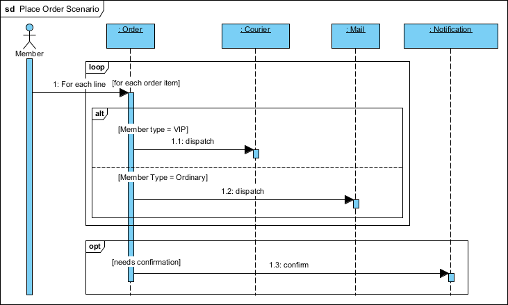
The diagram illustrates three distinct layers of logic:
- Iteration: Handling multiple line items in a single order.
- Conditional Dispatching: Routing the order based on user status (VIP vs. Ordinary).
- Optional Notification: Triggering a confirmation message only when necessary.
Step-by-Step Modeling Concepts
To build this diagram effectively, we utilize three specific UML interaction fragments: loop, alt, and opt. Let’s break down how each functions within the architecture.
1. The Loop Fragment (Iterative Processing)
When a Member places an order, it rarely contains just one item. The system must process every line item individually. In UML, this is represented by the loop fragment.
In our diagram, the loop box encapsulates the processing request. It contains a guard condition [for each order item], which signifies that the messages inside the box are repeated for every item found in the order cart. This prevents the need to draw repetitive arrows for every single product.
2. The Alt Fragment (Conditional Branching)
Once the system is inside the loop processing an item, it must decide how to fulfill that order. This decision depends on the Member type.
We use the alt (alternative) fragment to model this branching logic. The diagram splits into two distinct regions:
- Region 1 (VIP): If
[Member type = VIP], the:Ordercomponent dispatches the item via the:Courierservice. - Region 2 (Ordinary): If
[Member Type = Ordinary], the:Ordercomponent dispatches the item via the:Mailservice instead.
Visually, a dashed line separates these conditions, clearly indicating that only one path will be taken for a specific order item.
3. The Opt Fragment (Optional Behavior)
Not every order requires a confirmation message. This behavior is optional and depends on a specific trigger: [needs confirmation]. This is modeled using the opt (optional) fragment.
The opt fragment sits outside the processing loop (or adjacent to it), ensuring that the :Notification service is only triggered if the condition is met. This keeps the diagram clean and separates “happy path” processing from “exception” or “optional” handling.
Technical Implementation Guide
When documenting this architecture using Visual Paradigm, it is crucial to structure the fragments hierarchically. The diagram demonstrates that alt and opt fragments can be nested or positioned relative to the loop to define exactly when the logic applies.
Below is a representation of the logical flow that should be implemented in the modeling tool:
Member -> Order: 1. Place Order (containing items)

Order -> Order: loop [for each order item]
    Order -> Order: alt [Member type = VIP]
        Order -> Courier: 1.1: dispatch
    Order -> Order: alt [Member Type = Ordinary]
        Order -> Mail: 1.2: dispatch
Order -> Notification: 1.3: confirm [if needs confirmation]
Best Practices for Complex Workflows
To ensure your UML diagrams serve as accurate blueprints for development, adhere to these rules:
- Be Explicit with Guards: Never leave a condition implied. Always write
[Condition]clearly in the fragment headers. For example, explicitly stating[Member type = VIP]prevents ambiguity. - Nesting Matters: Notice the hierarchy. The
altfragment sits inside theloop, meaning the branching decision happens for every item. If theoptfragment is outside the loop, the confirmation might only happen once for the whole order. - Keep it Readable: If a diagram becomes too crowded with nested fragments, consider breaking it down into separate diagrams or using “Interaction Uses” to reference sub-processes.
Conclusion
The Place Order Scenario demonstrates that effective UML modeling is about capturing the decision-making intelligence of a system. By utilizing Visual Paradigm’s support for loop, alt, and opt combined fragments, you can transform vague requirements into precise technical specifications. When documenting complex workflows, always remember to be explicit with guards and maintain a clear hierarchy to reduce ambiguity and prevent logic errors before a single line of code is written.