

Designing complex systems requires a structured approach to behavior. One of the most powerful tools available for this purpose is the state machine diagram. Often referred to simply as a state diagram, this visual language helps engineers map out how a system behaves under different conditions. Without a clear map, logic can become tangled, leading to bugs that are difficult to trace. By understanding the fundamental components and patterns, you can transform chaotic requirements into a reliable, predictable architecture.
This guide explores the core mechanics of state modeling. We will break down the anatomy of the diagram, examine advanced patterns, and discuss best practices for maintaining clarity throughout the development lifecycle. Whether you are designing a user interface flow or a backend protocol handler, a solid grasp of state transitions is essential.
Understanding the Core Components 🧩
A state diagram represents the dynamic behavior of a class or system. It focuses on the sequence of states that an object goes through in response to events. To build an accurate model, you must first understand the building blocks. Each element serves a specific purpose in defining the lifecycle of the object.
1. States
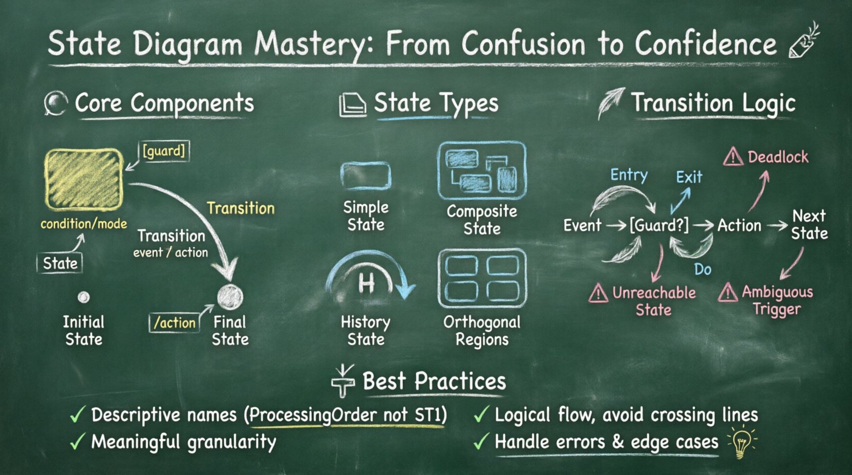
A state represents a condition or situation during the life of an object in which it satisfies some condition, performs some activity, or waits for some event. Visually, these are typically depicted as rounded rectangles. States are not just placeholders; they imply specific behaviors or data conditions.
- Simple State: A state that has no sub-states. It is atomic and cannot be broken down further.
- Composite State: A state that contains other sub-states. This allows for hierarchy and complexity management.
- Initial State: The starting point of the diagram. It is usually represented by a solid circle.
- Final State: The termination point of the lifecycle. It is shown as a double-bordered circle.
2. Transitions
Transitions define how the system moves from one state to another. They are the arrows connecting the states. A transition is triggered by an event. Without a transition, a system remains static. Transitions ensure that the system reacts to changes in its environment.
3. Events
An event is something that happens at a specific point in time. It triggers a transition. Events can be signals, messages, or time-based occurrences. In a diagram, events are listed near the transition arrow.
4. Guards and Actions
Not all transitions are available at all times. Guards are conditions that must be true for the transition to occur. Actions are the activities performed when the transition happens or when entering/exiting a state.
| Component | Function | Visual Representation |
|---|---|---|
| State | Defines a condition or mode | Rounded Rectangle |
| Transition | Connects states; defines movement | Arrow with Label |
| Event | Trigger for the transition | Text on Arrow |
| Guard | Condition required to proceed | Text in Brackets [ ] |
| Action | Activity performed during transition | Text after Slash / |
Deep Dive into State Types 🏗️
As systems grow, simple states are often insufficient. You need mechanisms to handle complexity without cluttering the diagram. Understanding the different types of states is crucial for scalable design.
Composite States
A composite state contains a hierarchy of sub-states. This is similar to a folder containing files. Inside a composite state, you can have multiple parallel states or sequential states. This reduces visual noise by grouping related behaviors together.
- Decomposition: Breaking a large state into smaller, manageable chunks.
- Context: The parent state provides context for the child states.
- Entry/Exit: Actions can be defined at the composite level, applying to all sub-states.
Orthogonal Regions
nSometimes, a system needs to track multiple independent behaviors simultaneously. For example, a device might be charging while displaying the time. Orthogonal regions allow you to define parallel state machines within a single composite state. The system must be in one state from Region A and one state from Region B at the same time.
History States
When a composite state is exited and later re-entered, the system often needs to remember where it left off. A history state allows the system to return to the last active sub-state instead of restarting from the initial sub-state. This is denoted by a semi-circle arrow symbol.
- Deep History: Returns to the last active state in the entire hierarchy.
- Shallow History: Returns to the last active sub-state of the top level.
Transitions and Event Handling 🔄
The logic of the system lives in the transitions. A poorly defined transition can lead to deadlocks or unreachable states. It is vital to define clear triggers and outcomes.
Trigger Conditions
Every transition needs a trigger. This is the event that initiates the move. In a software context, this might be a user click, a network response, or a timer expiration. Ensure that triggers are unique enough to avoid ambiguity.
Guard Clauses
Guards add logic to transitions. They act as filters. If the guard condition evaluates to false, the transition is ignored, even if the event occurs. This is essential for preventing invalid state changes.
Example: A login state might have a transition to a dashboard state. However, a guard condition might check if the password is correct before allowing the move.
Effect Actions
What happens during the move? Actions are the side effects of a transition. They can be:
- Entry Action: Executed immediately upon entering a state.
- Exit Action: Executed immediately upon leaving a state.
- Do Action: An activity that runs continuously while the system remains in the state.
Designing for Maintainability 📝
A diagram is not just a one-time artifact. It evolves as requirements change. To keep diagrams useful over time, follow specific design principles.
1. Naming Conventions
Names should be clear and descriptive. Avoid abbreviations that are not industry-standard. A state named ST1 is confusing compared to ProcessingOrder. Use nouns for states and verbs for transitions where appropriate.
2. Granularity Control
Do not make states too granular. If a state represents a single line of code, it is likely too small. Aim for states that represent a meaningful phase of behavior. Conversely, do not make states too broad. A state that encompasses the entire application logic is useless.
3. Avoid Spaghetti Logic
Transitions should flow logically. If lines cross constantly, the diagram is hard to read. Use hierarchy to group related transitions. If a state has too many outgoing transitions, consider splitting it into sub-states.
| Principle | Good Practice | Poor Practice |
|---|---|---|
| Clarity | States are named descriptively | States are labeled with codes |
| Flow | Transitions follow a logical path | Transitions cross randomly |
| Completeness | All necessary events are handled | Events lead to undefined states |
| Consistency | Standard notation is used throughout | Mixing different diagram styles |
Common Pitfalls and How to Avoid Them ⚠️
Even experienced designers make mistakes. Recognizing common errors early saves significant time during implementation.
Deadlocks
A deadlock occurs when the system reaches a state where no transitions are possible, but the system is not in a final state. This usually happens when a transition guard is never satisfied. Always verify that every state has at least one valid path to the final state or back to a valid loop.
Unreachable States
If a state cannot be reached from the initial state, it serves no purpose. This often happens when creating new states without updating the entry transitions. Perform a reachability analysis to ensure every state is accessible.
Ambiguous Transitions
If two transitions are triggered by the same event from the same state, the system does not know which one to take. Use guards to differentiate them. If guards are not enough, ensure the events are distinct.
Ignoring Error Handling
Systems fail. A state diagram should account for failure modes. Define states for error recovery or timeout scenarios. Do not assume everything will proceed smoothly.
Advanced Patterns for Complex Systems 🚀
As the complexity increases, standard diagrams may become unwieldy. Advanced patterns help manage this scale.
State Hierarchy
Use hierarchy to reduce duplication. If multiple states require the same entry action, define the action at the parent composite state. This ensures consistency and reduces maintenance overhead.
Event Bubbling
In a hierarchical state machine, if a state does not handle an event, the event can bubble up to the parent state. This allows for shared behavior without repeating code or definitions. It is a powerful way to manage common logic across different parts of the system.
Parallelism
Some systems operate in multiple modes at once. Orthogonal regions allow you to model these independent processes within a single state diagram. For instance, a media player can be in a Playing state in one region and a Buffering state in another.
Implementation Considerations 💻
Once the diagram is complete, the next step is implementation. While this guide does not cover specific tools, the principles of mapping diagrams to code remain constant.
Code Generation
Some environments allow automatic generation of code from state diagrams. This reduces manual errors and ensures the code matches the design. However, generated code can be verbose. Review the output to ensure it meets performance requirements.
Manual Implementation
When coding manually, map each state to a class or enum. Transitions become methods or switch statements. Ensure the naming conventions match the diagram to make debugging easier.
Documentation Alignment
The diagram is a form of documentation. If the code changes, the diagram must be updated. Outdated diagrams are worse than no diagrams because they mislead developers. Treat the diagram as living documentation.
Testing the State Machine 🧪
Testing state machines requires a different approach than testing standard functions. You need to verify the sequence of states, not just the output of a function.
- Path Testing: Verify that every transition path can be traversed.
- State Coverage: Ensure every state is entered at least once.
- Edge Cases: Test transitions that are guarded by complex conditions.
- Recovery: Test how the system recovers from invalid states or errors.
Conclusion on Modeling 🏁
Building a reliable system starts with a clear understanding of its behavior. State diagrams provide that clarity. They force you to think about every possible condition and reaction before writing code. By avoiding common pitfalls and adhering to best practices, you create models that are robust and easy to maintain.
The journey from confusion to confidence comes with practice. Start with simple diagrams and gradually introduce complexity as needed. Remember that the goal is not just to draw a picture, but to communicate logic effectively. With a well-structured state machine, you can ensure your system behaves predictably, even in complex scenarios.