


In the rapidly evolving world of software architecture and system design, modularity, clarity, and speed are critical to successful project delivery. One of the most powerful tools in a developer or architect’s toolkit is the UML (Unified Modeling Language) Component Diagram, which visually represents the modular structure of a system, illustrating how components interact and depend on one another.
With the recent major upgrade to AI UML Component Diagram generation in Visual Paradigm’s AI Chatbot (see Major Upgrade to AI UML Component Diagram Generation in Visual Paradigm AI Chatbot), the process of creating, refining, and iterating on component diagrams has undergone a transformative shift—thanks to artificial intelligence (AI) and generative AI (GenAI) technologies.
This comprehensive guide dives deep into the key concepts of UML Component Diagrams, explores real-world examples, provides best practices and guidelines, and explains how Visual Paradigm’s AI-powered diagramming engine is revolutionizing visual modeling for software teams, architects, and students alike.
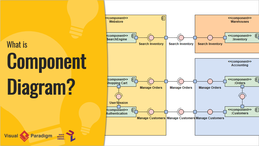
🔹 What Is a UML Component Diagram?
A UML Component Diagram is a structural diagram that models the modular architecture of a software system. It shows how different components—such as libraries, modules, services, or executables—interact with each other through interfaces and dependencies.
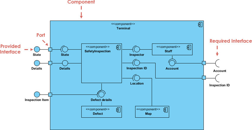
✅ Key Elements of a UML Component Diagram:
-
Component: A modular, self-contained unit of functionality (e.g., Payment Service, User Authentication Module).
-
Interface: A contract defining how a component communicates with others (e.g.,
PaymentProcessorinterface). -
Dependency: A relationship indicating that one component relies on another (e.g.,
BookingServicedepends onPaymentService). -
Port: A point of interaction between a component and its environment.
-
Connector: A line showing how components communicate via their ports.
💡 Why Use Component Diagrams?
Clarify system modularity and separation of concerns.
Aid in team collaboration and system documentation.
Support scalable, maintainable, and testable designs.
Serve as a foundation for C4 modeling and architectural decision-making.
🔹 Why AI Is a Game-Changer in UML Component Diagram Creation
Traditional diagramming requires manual effort, deep domain knowledge, and time—especially when translating complex system descriptions into visual models. Enter AI-powered diagram generation.
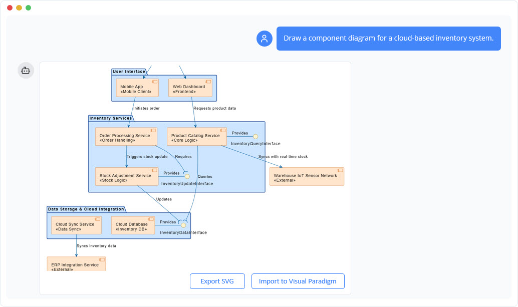
Visual Paradigm’s AI Chatbot now leverages generative AI (GenAI) to convert natural language prompts into accurate, standardized UML Component Diagrams. This capability is detailed in the article AI-Powered Component Diagrams with Visual Paradigm Chatbot, which highlights how users can simply describe their system in plain English and receive a fully rendered diagram in seconds.

For example, typing:
“Create a component diagram for a car park booking system with a user interface, booking service, payment service, and database.”
…results in a fully structured diagram with components, interfaces, and dependencies—automatically generated and validated.
This automation dramatically reduces the time-to-first-diagram and eliminates the common bottleneck in project kickoffs.
🚀 See how AI accelerates project initiation: Why Every Team Needs an AI Diagram Maker for Faster Project Kickoff
🔹 How Visual Paradigm’s AI Component Generator Works
Visual Paradigm’s AI-powered diagram generator (see AI Diagram Generator: Complete C4 Model Support) is built on advanced language models trained on architectural patterns and UML standards. Here’s how it enhances the visual modeling process:
✨ Key Features of the AI Generator:
-
Natural Language Input
Users describe system architecture in plain English—no need to learn UML syntax upfront. -
Automatic Component Recognition
AI identifies components, interfaces, and dependencies from the prompt. -
Standardized UML Compliance
Diagrams follow UML 2.5+ standards, ensuring consistency and professionalism. -
Iterative Refinement
Users can refine diagrams through follow-up prompts like:-
“Add a notification service that sends emails after booking.”
-
“Make the payment service use a third-party API.”
-
-
Integration with C4 Modeling
Visual Paradigm now supports full C4 model support, enabling users to generate context, container, component, and code-level diagrams (see Visual Paradigm Full C4 Model Support Release).This is particularly useful for enterprise architecture, where layered abstraction is essential.
-
AI-Driven Validation & Suggestions
The AI checks for logical consistency, suggests missing interfaces, and warns about circular dependencies.
📌 Pro Tip: Use the AI to prototype architecture before coding. This helps catch design flaws early.
🔹 Real-World Example: Building a Car Park Booking System
The Comprehensive Tutorial: Generating and Modifying C4 Component Diagrams with AI provides a step-by-step walkthrough of creating a C4 component diagram for a car park booking system using Visual Paradigm’s AI chatbot.
Step-by-Step Process:
-
Prompt the AI:
“Generate a C4 component diagram for a car park booking system with a web frontend, booking service, payment service, and database.”
-
AI Response:
-
Automatically creates components:
Web UI,Booking Service,Payment Service,Database. -
Adds interfaces:
BookParking,ProcessPayment,SaveBooking. -
Draws dependencies:
Booking Service → Payment Service,Booking Service → Database.
-
-
Refine with AI:
-
Add a
Notification Servicethat sends emails viaSendEmailinterface. -
Ask: “Make the payment service use Stripe API.”
-
-
Export & Share:
-
Diagram can be exported as PNG, SVG, or embedded in documentation.
-
This tutorial demonstrates how AI transforms architectural design from a manual chore into an interactive, conversational process—ideal for both students learning software design and professional architects.
🎓 Ideal for students: Mastering AI-Generated UML Component Diagrams: A Comprehensive Guide offers structured learning paths and best practices.
🔹 Best Practices & Guidelines for Effective UML Component Diagrams
Even with AI assistance, following best practices ensures your diagrams remain clear, accurate, and useful.
✅ Guidelines for High-Quality Component Diagrams:
| Principle | Best Practice | Source |
|---|---|---|
| Modularity | Keep components focused on a single responsibility. Avoid monolithic components. | UML Component Diagram Tutorial: Building Modular Software Systems |
| Interface-Driven Design | Define interfaces explicitly. Use <<interface>> stereotype. |
Visual Paradigm Full C4 Model Support Release |
| Avoid Over-Dependency | Minimize direct dependencies between components. Use abstraction layers. | AI-Powered System Design with Visual Paradigm |
| Use Clear Naming | Use descriptive, consistent names (e.g., UserAuthenticationService, not AuthService1). |
Mastering AI-Generated UML Component Diagrams |
| Iterate with AI | Use AI to generate, review, refine, and validate diagrams continuously. | Comprehensive Tutorial: Generating and Modifying C4 Component Diagrams |
🛠️ Tip: Use AI to generate a first draft, then manually validate and enhance it for production use.
🔹 Why Visual Paradigm’s AI Component Generator Is a Must-Have Tool
Visual Paradigm’s AI-powered diagramming suite isn’t just a novelty—it’s a strategic advantage for modern software teams.
✅ Advantages of Using Visual Paradigm’s AI Generator:
-
Faster Project Kickoff: Eliminate the “blank canvas” phase. Generate diagrams in seconds.
-
Democratizes Architecture: Students and junior developers can create professional diagrams without deep UML training.
-
Enhances Collaboration: Teams can discuss architecture using visual models generated from shared language.
-
Supports Agile & DevOps: Rapidly prototype and iterate on architecture during sprints.
-
Integrates with Existing Workflows: Diagrams can be exported, version-controlled, and embedded in Confluence, Jira, or GitHub.
🔥 See how AI is transforming system design: AI-Powered System Design with Visual Paradigm
🔹 Conclusion: The Future of Visual Modeling Is AI-Powered
The integration of generative AI into UML and C4 modeling—especially through Visual Paradigm’s AI Chatbot—marks a turning point in software architecture. What once took hours of manual effort can now be accomplished in minutes, with higher accuracy, consistency, and creativity.
Whether you’re a student learning software design, a developer building modular systems, or a system architect documenting complex enterprise solutions, Visual Paradigm’s AI-powered component diagram generator is an indispensable tool.
By combining natural language input, UML standards compliance, C4 modeling support, and iterative refinement, it empowers teams to design better systems, faster.
📌 Start your journey today:
Try the AI Chatbot: Major Upgrade to AI UML Component Diagram Generation in Visual Paradigm AI Chatbot
Learn step-by-step: Comprehensive Tutorial: Generating and Modifying C4 Component Diagrams with AI
📚 Additional Resources
-
UML Component Diagram Tutorial: Building Modular Software Systems (AI Focus) – Hands-on video guide.
-
AI-Powered Component Diagrams with Visual Paradigm Chatbot – In-depth overview of AI capabilities.
-
Mastering AI-Generated UML Component Diagrams: A Comprehensive Guide – Technical deep dive.
-
Visual Paradigm Full C4 Model Support Release – Official release notes.
🌟 Final Thought:
“The future of software architecture isn’t just about writing code—it’s about modeling it clearly, quickly, and collaboratively. With AI, that future is already here.”
Leverage Visual Paradigm’s AI-powered UML Component Diagram generator to design smarter, build faster, and communicate more effectively—starting today.