
The behavior of an entity is not only a direct consequence of its inputs, but it also depends on its preceding state. The past history of an entity can best be modeled by a finite state machine diagram or traditionally called automata. UML State Machine Diagrams (or sometimes referred to as state diagram, state machine or state chart) show the different states of an entity. State machine diagrams can also show how an entity responds to various events by changing from one state to another. State machine diagram is a UML diagram used to model the dynamic nature of a system.

🚀 Learn UML Faster, Better and Easier
Are you looking for a Free UML tool for learning UML faster, easier and quicker? Visual Paradigm Community Edition is a UML software that supports all UML diagram types. It is an international award-winning UML modeler, and yet it is easy-to-use, intuitive & completely free.
Why State Machine Diagrams?
State machine diagrams typically are used to describe state-dependent behavior for an object. An object responds differently to the same event depending on what state it is in. State machine diagrams are usually applied to objects but can be applied to any element that has behavior to other entities such as: actors, use cases, methods, subsystems, systems, etc., and they are typically used in conjunction with interaction diagrams (usually sequence diagrams).
Practical Example: Bank Account Withdrawal
Consider you have $100,000 in a bank account. The behavior of the withdraw function would be:
balance := balance - withdrawAmount;
provided that the balance after the withdrawal is not less than $0; this is true regardless of how many times you have withdrawn money from the bank. In such situations, the withdrawals do not affect the abstraction of the attribute values, and hence the gross behavior of the object remains unchanged.
However, if the account balance would become negative after a withdrawal, the behavior of the withdraw function would be quite different. This is because the state of the bank account is changed from positive to negative; in technical jargon, a transition from the positive state to the negative state is fired.
💡 Note: The abstraction of the attribute value is a property of the system, rather than a globally applicable rule. For example, if the bank changes the business rule to allow the bank balance to be overdrawn by $2,000, the state of the bank account will be redefined with the condition that the balance after withdrawal must not be less than $2,000 in deficit.
Key Distinction
| Diagram Type | Scope |
|---|---|
| State Machine Diagram | Describes all events, states, and transitions for a single object |
| Sequence Diagram | Describes the events for a single interaction across all objects involved |
Basic Concepts of State Machine Diagram
What is a State?
“A state is an abstraction of the attribute values and links of an object. Sets of values are grouped together into a state according to properties that affect the gross behavior of the object.” — Rumbaugh
State Notation

Characteristics of State Machine Notations
-
A state occupies an interval of time
-
A state is often associated with an abstraction of attribute values of an entity satisfying some condition(s)
-
An entity changes its state not only as a direct consequence of the current input, but it is also dependent on some past history of its inputs
State Definition
A state is a constraint or a situation in the life cycle of an object, in which a constraint holds, the object executes an activity or waits for an event.
A state machine diagram is a graph consisting of:
-
States (simple states or composite states)
-
State transitions connecting the states
Example:

Characteristics of State
-
States represent the conditions of objects at certain points in time
-
Objects (or Systems) can be viewed as moving from state to state
-
A point in the lifecycle of a model element that satisfies some condition, where some particular action is being performed or where some event is waited
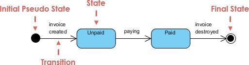
Initial and Final States
| State Type | Symbol | Description |
|---|---|---|
| Initial State | ● Solid Circle | Known as an initial pseudo-state; a transition from this state shows the first real state |
| Final State | ◎ Concentric Circles | Represents termination; an open loop state machine represents an object that may terminate before the system terminates |
Example:

📌 Note: A closed loop state machine diagram does not have a final state; if it is the case, then the object lives until the entire system terminates.
Events
An event signature is described as Event-name (comma-separated-parameter-list). Events appear in the internal transition compartment of a state or on a transition between states.
Four Types of Events
-
Signal Event – corresponding to the arrival of an asynchronous message or signal
-
Call Event – corresponding to the arrival of a procedural call to an operation
-
Time Event – occurs after a specified time has elapsed
-
Change Event – occurs whenever a specified condition is met
Characteristics of Events
-
Represents incidents that cause objects to transition from one state to another
-
Internal or External Events trigger some activity that changes the state of the system and of some of its parts
-
Events pass information, which is elaborated by Objects operations. Objects realize Events
-
Design involves examining events in a state machine diagram and considering how those events will be supported by system objects
Transitions
Transition lines depict the movement from one state to another. Each transition line is labeled with the event that causes the transition.
Key Principles
-
Viewing a system as a set of states and transitions between states is very useful for describing complex behaviors
-
Understanding state transitions is part of system analysis and design
-
A Transition is the movement from one state to another state
Transition Sequence
-
An element is in a source state
-
An event occurs
-
An action is performed
-
The element enters a target state
Additional Notes
-
Multiple transitions occur either when different events result in a state terminating or when there are guard conditions on the transitions
-
A transition without an event and action is known as an automatic transition
Actions vs. Activities
| Feature | Action | Activity |
|---|---|---|
| Nature | Executable atomic computation | Non-atomic or ongoing computation |
| Examples | Operation calls, object creation/destruction, sending signals | Complex behaviors that may run for extended periods |
| Interruptibility | Not interruptible – completes without interruption | May be interrupted by events; may run to completion or continue indefinitely |
| Association | Associated with transitions | Associated with states |
Characteristics of Actions and Activities
-
States can trigger actions
-
States can have a second compartment that contains actions or activities performed while an entity is in a given state
-
An action is an atomic execution and therefore completes without interruption
-
Five triggers for actions: On Entry, Do, On Event, On Exit, and Include
-
An activity captures complex behavior that may run for a long duration – An activity may be interrupted by events, in which case it does not complete; occur when an object arrives in a state
Simple State Machine Diagram Notation
Entry and Exit Actions
Entry and Exit actions specified in the state. It must be true for every entry/exit occurrence. If not, then you must use actions on the individual transition arcs.
| Action Type | Notation | When Executed |
|---|---|---|
| Entry Action | entry / action |
Executed on entry into state |
| Exit Action | exit / action |
Executed on exit from state |
Example – Entry/Exit Action (Check Book Status)
This example illustrates a state machine diagram derived from a Class – “BookCopy”:

Key Notes:
-
This state machine diagram shows the state of an object
myBkCopyfrom aBookCopyclass -
Entry action: any action that is marked as linked to the entry action is executed whenever the given state is entered via a transition
-
Exit action: any action that is marked as linked to the exit action is executed whenever the state is left via a transition
🤖 Master Complex Object Lifecycles with AI
State machines are essential for modeling event-driven behavior, but nested substates and concurrent regions can be challenging to design manually. Visual Paradigm’s AI tools simplify this by transforming your behavioral logic into precise UML State Charts—complete with triggers, guards, and entry/exit actions.
AI-Enabled Platforms
| Platform | Capability |
|---|---|
| VP Desktop | Use the integrated AI assistant to generate and refine state-dependent logic directly within the UML modeler |
| AI Chatbot | Describe your object’s states and transitions to the AI Chat for instant, editable diagram generation |
Smart Behavioral Design Features
🔄 Transition Discovery: AI automatically identifies states and transitions from your system requirements
🛡️ Time Saving: Generate diagram in one click, few seconds
Learn More about AI State Diagramming | Full AI Ecosystem
Substates and Composite States
A simple state is one which has no substructure. A state which has substates (nested states) is called a composite state.
Key Rules for Substates
-
Substates may be nested to any level
-
A nested state machine may have at most one initial state and one final state
-
Substates are used to simplify complex flat state machines by showing that some states are only possible within a particular context (the enclosing state)
Substate Example – Heater
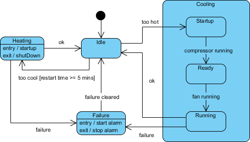
Testing Ideas Derived from State Machine Diagrams
State Machine Diagrams are often used for deriving testing cases. Here is a list of possible test ideas for the Heater example:
-
Idle state receives Too Hot event
-
Idle state receives Too Cool event
-
Cooling/Startup state receives Compressor Running event
-
Cooling/Ready state receives Fan Running event
-
Cooling/Running state receives OK event
-
Cooling/Running state receives Failure event
-
Failure state receives Failure Cleared event
-
Heating state receives OK event
-
Heating state receives Failure event
History States
Unless otherwise specified, when a transition enters a composite state, the action of the nested state machine starts over again at the initial state (unless the transition targets a substate directly).
History states allow the state machine to re-enter the last substate that was active prior to leaving the composite state.
History State Example

💡 Use Case: History states are particularly useful when modeling user interfaces or workflows where users may leave and return to a complex state without losing their progress.
Concurrent States
As mentioned above, states in state machine diagrams can be nested. Related states can be grouped together into a single composite state. Nesting states inside others is necessary when an activity involves concurrent sub-activities.
Concurrent State Machine Diagram Example – Auction Process
In this example, the state machine first entering the Auction requires a fork at the start into two separate start threads. Each substate has an exit state to mark the end of the thread. Unless there is an abnormal exit (Canceled or Rejected), the exit from the composite state occurs when both substates have exited.
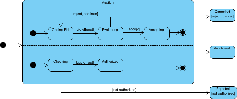
Key Characteristics of Concurrent States
-
Represent parallel execution paths within a composite state
-
Use fork/join notation to split and synchronize concurrent flows
-
Each concurrent region operates independently but contributes to the overall state behavior
-
Exit from the composite state occurs only when all concurrent substates have completed
✏️ Try to Draw UML State Machine Diagram Now
You’ve learned what a State Machine Diagram is and how to draw a State Machine Diagram. It’s time to draw a State Machine Diagram of your own.
Get Visual Paradigm Community Edition, a free UML software, and create your own State Machine Diagram with the free State Machine Diagram tool. It’s easy-to-use and intuitive.
Download Visual Paradigm Community Edition
AI-Powered State Diagram Generation
Visual Paradigm’s AI simplifies state diagram generation by converting natural language descriptions into standards-compliant UML models in seconds. You can describe an object’s lifecycle—such as an online order or a support ticket—and the AI automatically identifies the necessary states, transitions, triggers, and guard conditions.
Key Features for State Diagrams
✨ Natural Language to Diagram: Instantly generate complete UML State Machine Diagrams from simple text prompts
💬 Conversational Refinement: Use a chatbot interface to iteratively modify your diagram by adding substates, renaming elements, or refining transitions through simple commands
🧠 Intelligent Modeling Support: The AI includes advanced behavioral modeling features such as entry/exit actions, event triggers, and guard conditions
🗂️ Logical Organization: Features like intelligent clustering automatically group related states, while an automated layout engine ensures the diagram remains clean and readable
✅ Design Validation: You can ask the AI to analyze your diagram for logical flaws, such as “dead-end” states or unhandled events in specific states
The AI Ecosystem
Visual Paradigm integrates its AI across several platforms to provide a cohesive modeling experience:
Integrated Platforms & Capabilities
| Platform | Key Benefit |
|---|---|
| Integrated Desktop & Online Platforms | Start a diagram using the AI Chatbot or the online editor and seamlessly import it into the Visual Paradigm Desktop app for advanced code engineering and team collaboration |
| Documentation on Demand | Automatically generate detailed project reports, summaries, and technical documentation based on your visual models |
| Broad Notation Support | Beyond state diagrams, the AI supports over 40 diagram types including UML, BPMN, SysML, and ArchiMate |
| Inter-Model Traceability | Link your state diagrams to other project artifacts like use cases or user stories to maintain a single source of truth across your system architecture |
💬 Would you like to see an example prompt for generating a specific type of state machine? Just ask!
- 📚 Reference List
- What is State Machine Diagram?: Comprehensive guide to understanding UML State Machine Diagrams, their notation, components, and practical usage in system modeling.
- Mastering UML State Machine Diagrams with AI-Powered Visual Modeling: Learn how AI tools enhance state machine diagram creation, modeling efficiency, and behavioral design accuracy.
- Create UML State Diagrams in Seconds with AI: Discover how to generate UML state diagrams quickly using AI-powered tools that convert natural language descriptions into formal models.
- AI Diagram Generation: Visual Paradigm’s AI-powered feature for automatic diagram creation from natural language prompts across multiple UML notation types.
- AI Chatbot for Diagramming: Interactive AI assistant that helps generate and refine UML diagrams through conversational commands and iterative feedback.
- AI Chatbot Documentation: Official documentation and usage guidelines for leveraging the AI Chatbot to create, modify, and validate UML diagrams.
- Enhanced AI State Machine Diagram Generation: Release notes detailing improved AI capabilities for state diagram creation, including better transition detection and guard condition handling.
- AI State Diagram Enhancements: Technical overview of updates to AI-powered state machine modeling features and performance improvements.
- UML State Machine Diagram: A Definitive Guide to Modeling Object Behavior with AI: Comprehensive documentation on using AI to model object behavior through state machines, including best practices and examples.
- AI Composite Structure Diagram Generator: Generate UML composite structure diagrams instantly across Desktop, Chat, and OpenDocs platforms using AI assistance.
- What Makes Visual Paradigm’s AI Chatbot Different: Blog post explaining the unique advantages of Visual Paradigm’s AI chatbot for diagramming, including context-awareness and technical accuracy.
- Guide to Powered UML Diagram Generation: Vietnamese-language guide to AI-powered UML diagram generation features and workflows.
- Comprehensive Review: Visual Paradigm’s AI Diagram Generation Features: Third-party review evaluating Visual Paradigm’s AI diagramming capabilities, usability, and integration features.
- How Visual Paradigm’s AI-Powered Ecosystem Transforms UML Development: Article exploring how AI integration transforms UML development workflows, collaboration, and model-driven engineering practices.
-
🎯 Ready to get started? Download Visual Paradigm Community Edition today and begin modeling dynamic system behavior with professional-grade State Machine Diagrams—powered by intuitive design and intelligent AI assistance.