Welcome to the world of software architecture. You are likely here because you have encountered the term “State Machine Diagram” and felt a mix of curiosity and intimidation. It is a common sentiment. Many newcomers to engineering believe these diagrams belong to a secret club reserved for senior architects or hardware specialists. They imagine complex charts that take hours to draw and never actually get used in production code.
This guide aims to strip away that noise. We will look at the state machine diagram not as a theoretical artifact, but as a practical tool for organizing logic. By the end, you will understand when to use them, how they differ from simple if-else blocks, and why they are often the foundation of robust applications. Let us dive into the mechanics of Finite State Machines (FSM) without the fluff.
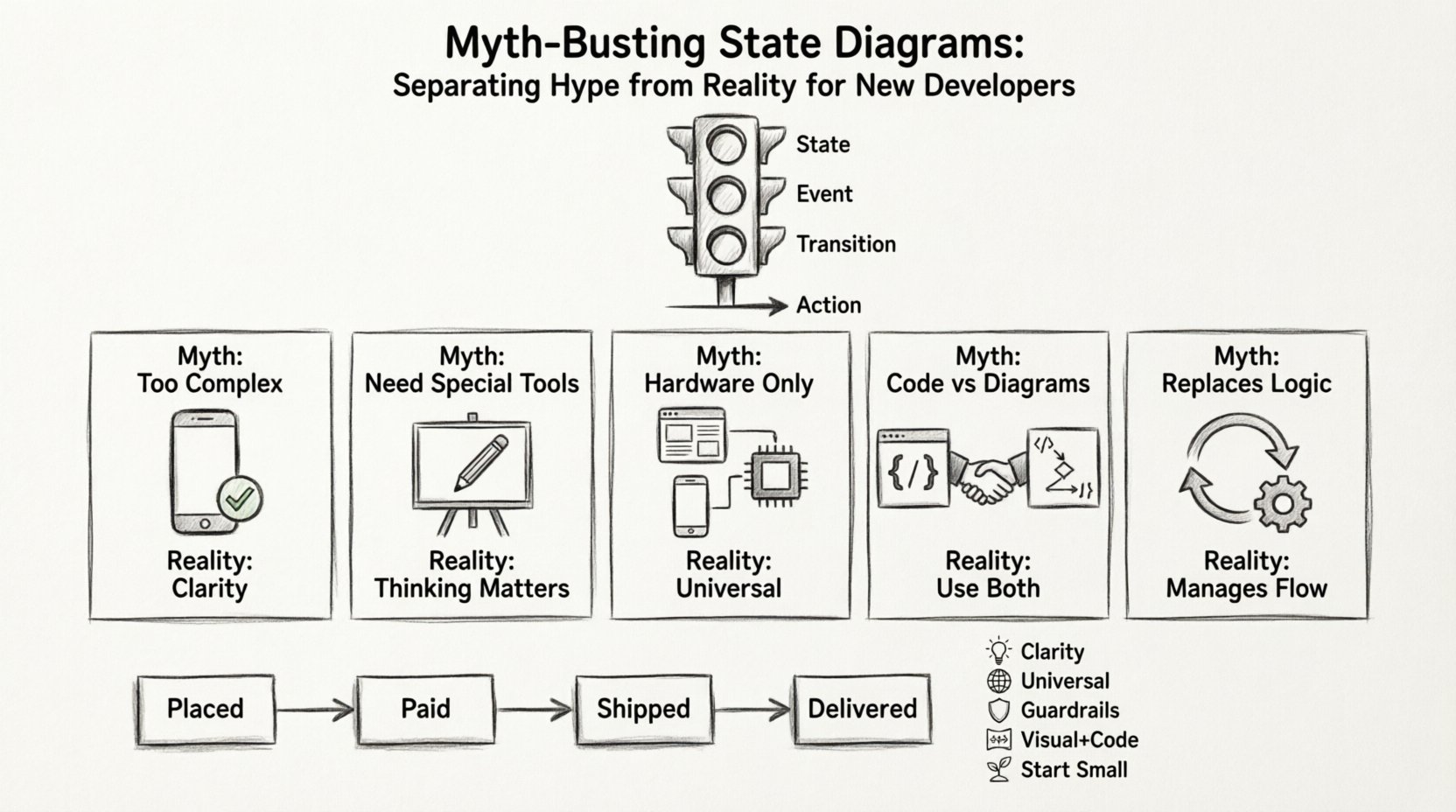
What Exactly Is a State Diagram? ⚙️
Before we bust myths, we must define the object. A state diagram, often associated with UML (Unified Modeling Language), is a visual representation of the different states a system can exist in and the transitions that occur between them. Think of a traffic light. It is either Red, Yellow, or Green. It does not exist as “Red and Green” simultaneously. It changes based on a timer or a sensor.
In software, this concept applies to everything from a login form to a robot vacuum cleaner. The core components are:
- State: A condition or situation during the life of an object during which it performs some activity or waits for some event.
- Event: Something that happens at a specific point in time which may cause a transition.
- Transition: The movement from one state to another triggered by an event.
- Action: The output or behavior that occurs when a transition happens.
When you model this, you create a map of behavior. This is the essence of the state machine.
Myth 1: State Diagrams Are Too Complex for Simple Apps 🤯
The most persistent myth is that you need a complex state machine for a complex application. Many developers write nested if statements and call it logic. While this works for a small script, it eventually becomes unmanageable. The state diagram is not about complexity; it is about clarity.
Consider a user registration process. Without a diagram, you might have code that checks: Is email valid? Is password valid? Is user new? Is user existing? Is email confirmed? These checks happen in various places. A state diagram forces you to define the valid statuses upfront:
- Created: User signed up, no email sent.
- Unverified: Email sent, waiting for click.
- Active: Email confirmed.
- Banned: Violation detected.
By visualizing these, you prevent logical errors. You cannot move from “Banned” to “Active” without going through a review process. The diagram enforces business rules visually before a single line of code is written.
Myth 2: You Need Specialized Tools to Use Them 🛠️
Some believe that drawing a state machine requires expensive enterprise software or specialized drawing applications. This is not true. The value lies in the thinking, not the drawing tool.
While visual editors exist, the logic can be documented in plain text or even code comments. The diagram is a mental model. If you can describe the flow of a process verbally, you can represent it as a state diagram. Here is a comparison of implementation approaches:
| Approach | Pros | Cons |
|---|---|---|
| Visual Diagrams | Easy to share, clear overview, good for documentation. | Can become outdated if not synced with code. |
| Code-Based State Machines | Always up to date, type-safe, executable. | Less immediately visual for non-coders. |
| Hybrid (Docs + Code) | Best of both worlds, clear intent, maintainable. | Requires discipline to maintain both. |
The goal is not to produce a pretty picture. The goal is to ensure your code logic is sound. Whether you draw it on a whiteboard or define it in a configuration file, the principle remains the same.
Myth 3: They Are Only for Embedded Hardware 🖥️
State machines originated in electrical engineering for circuit logic. Consequently, many web developers assume this is irrelevant to their work. This is a significant oversight. Modern web applications, mobile apps, and backend services all deal with status changes.
Consider an e-commerce order system. The order moves through states:
- Placed
- Paid
- Shipped
- Delivered
- Returned
Without a state machine, you might allow a “Refund” action on an order that is still “Placed”. You might try to “Ship” an order that hasn’t been “Paid”. A state machine diagram prevents these impossible actions by defining which transitions are valid. It acts as a guardrail for your application logic.
Myth 4: Code Is Better Than Diagrams 📝
Some argue that code is the only truth. Diagrams are just documentation. While code is executable, it is often hard to read the high-level flow from scattered functions. Diagrams provide a top-down view.
However, there is a middle ground. We do not need to choose one over the other. We use diagrams to design and code to implement. The diagram helps you spot edge cases. For example, if you draw the diagram and realize you have two arrows pointing to “Dead State” without a recovery path, you know you need to handle that error condition in the code.
When to rely on the diagram:
- Onboarding: Explaining a complex system to a new team member.
- Design Phase: Before writing the first function.
- Debugging: When the system behaves unexpectedly in a specific scenario.
- Documentation: For API contracts where state changes matter.
Myth 5: They Replace Logic Entirely 🧠
A state machine is not a magic wand. It does not write the business logic for you. It only manages the flow. If you have a complex calculation inside a state transition, the state diagram does not simplify that calculation. It simply ensures the calculation happens at the right time.
It is crucial to distinguish between flow control and business logic. The state diagram handles the flow. The functions called during transitions handle the logic. Confusing the two leads to bloated state definitions.
Technical Deep Dive: Hierarchical States 📉
One of the most powerful features of advanced state diagrams is the ability to nest states. This is known as a Composite State or Hierarchical State. This allows you to manage complexity without creating a spaghetti chart of hundreds of boxes.
Imagine a media player. It has states like Playing, Paused, and Stopped. But what if Playing has sub-states? It could be Buffering or Ready. If you flatten this, you have to define transitions for every combination. With hierarchy, you can define a global transition for Stopped that applies to all sub-states of Playing.
This reduces redundancy. You do not need to write the same logic for entering every sub-state. You can define an Entry Action for the parent state that initializes variables common to all children.
Key concepts to understand:
- Initial State: The default entry point when the composite state is entered.
- History State: Allows the system to return to the last active sub-state when re-entering the parent state.
- Final State: A terminal condition where the machine stops or resets.
When to Use State Diagrams in Your Workflow 📅
You should not draw a state diagram for every single function. It is a tool for specific scenarios. Use them when:
- Logic is Non-Linear: If the flow depends heavily on history (what happened before), a state machine is better than a linear script.
- Events Are Asynchronous: If your system waits for network responses or user input, states help manage the waiting periods without blocking the main thread.
- Multiple Actors Interact: If different users or systems trigger changes, a state machine ensures consistency regardless of who triggers the event.
- Compliance is Required: In regulated industries, having a visual audit trail of system states is often mandatory.
Common Pitfalls to Avoid ⚠️
Even with the right mindset, developers often make mistakes when implementing state logic. Here are the most common errors:
1. Ignoring the “Unhandled State”
Every state machine must handle events it does not expect. If you are in State A and receive Event X, but have no transition for it, the system should fail gracefully or log an error. Never assume the event will always be valid.
2. Overusing Events
Events are triggers, not data. Do not store complex data payloads in the event itself. Pass the data as parameters or update the context. The event should simply say “Something happened”.
3. Tying State to UI
A common mistake is making the state machine reflect the UI directly. The UI is a view of the state, not the state itself. If you have 10 screens, do not create 10 states. You might have one state that represents the “Data Fetching” phase, regardless of which screen is shown.
4. Forgetting Entry and Exit Actions
When a state is entered, you might need to fetch data. When exited, you might need to save data. These are Entry and Exit actions. Do not mix these logic steps into the transition. Keep them clean.
Real-World Example: A Smart Home Device 🏠
Let us look at a generic smart thermostat. It has a clear lifecycle.
- Idle: Waiting for a temperature change request.
- Heating: Actuator is on.
- Cooling: Fan is on.
- Off: System is dormant.
If the device is in Heating and the user sets the temperature lower than the current temp, the system transitions to Idle. If the user presses “Off”, it transitions to Off regardless of the current mode. This priority logic is best visualized in a diagram.
Without this, you might end up with code like:
if (mode == HEATING && target < current) {
  stopHeating();
}
if (mode == COOLING && target < current) {
  stopCooling();
}
// ... and so on
With a state machine, the Off state is a sink. Any command to turn off from any state leads there. The transitions are explicit.
How to Start Implementing Today 🏁
You do not need to rewrite your entire codebase. Start small. Pick one module that feels confusing. Identify the distinct statuses. Draw the boxes. Connect the arrows. Then, look at your code.
Does your code match the diagram? If not, refactor. This process is called refactoring to state. It often reveals that your logic was more fragile than you thought.
Steps to take:
- Identify the Context: What object has a status? (e.g., Order, User, Session).
- List the States: Write them down. Remove duplicates.
- List the Events: What causes changes? (e.g., Click, API Response, Timer).
- Draw the Transitions: Connect events to states.
- Code the Logic: Implement the transitions in your preferred language.
- Test the Edges: Try to break the machine. Send invalid events.
The Future of State Management 📈
The principles of state diagrams are evolving. Modern frameworks often include built-in state management tools that abstract the diagrammatic nature. However, the underlying theory remains the same. Whether you use a visual tool or a code library, understanding the Finite State Machine concept is vital.
As systems become more distributed and asynchronous, the need for clear state boundaries increases. Microservices, serverless functions, and edge computing all rely on predictable state transitions to ensure data consistency.
Summary of Key Takeaways 📝
To wrap up this deep dive, here are the core points to remember:
- Clarity over Complexity: Use diagrams to clarify logic, not to add burden.
- Universal Application: They apply to web, mobile, backend, and hardware.
- Guardrails: They prevent invalid states and actions.
- Visual + Code: Do not rely solely on one; use both for best results.
- Start Small: Apply the concept to one module before scaling.
State machine diagrams are not a magic solution, but they are a disciplined approach to problem-solving. By separating the state of your system from the logic that changes it, you create software that is easier to reason about, test, and maintain. The reality is that these diagrams are not hype; they are a foundational skill for writing reliable code.
Take the time to sketch your next complex module. You might find that the diagram solves the problem before you even start typing.