Understanding how systems talk to one another is fundamental to software architecture. When designing backend logic or microservices, visualizing the flow of data is not just helpful—it is essential. A communication diagram offers a clear way to map these interactions. Unlike other diagram types that focus heavily on time, this approach emphasizes the structural relationships between objects. This guide provides a deep dive into creating and interpreting these diagrams for modern system design.
What Is a Communication Diagram? 🤔
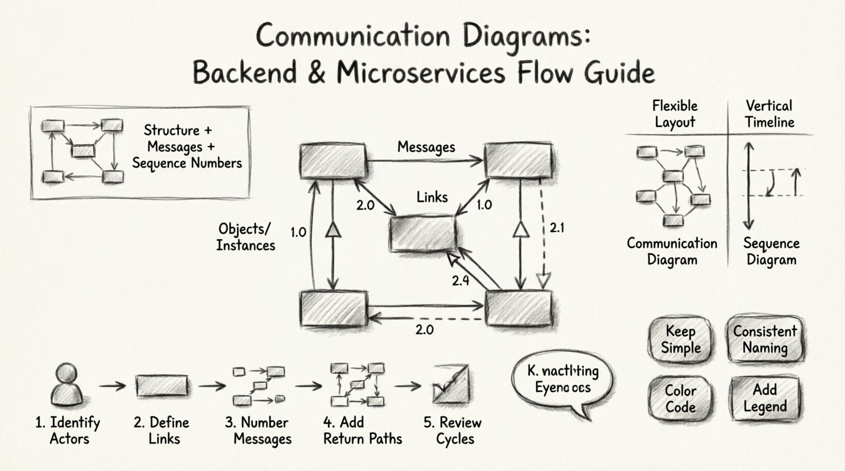
A communication diagram is a type of interaction diagram used in Unified Modeling Language (UML). It depicts how objects or components interact with each other to achieve a specific goal. The diagram highlights the links between objects and the messages passed along those links.
Here are the key characteristics:
- Focus on Structure: It shows the static topology of the system first.
- Focus on Messages: It details the flow of information between those structures.
- Sequence Numbering: It uses numbers to indicate the order of messages, rather than vertical position.
- Simplicity: It is often less cluttered than sequence diagrams for complex object networks.
For backend developers, this means you can see the entire network of dependencies in a single view. For microservices architects, it clarifies how Service A calls Service B, which might then call Service C.
Core Components of the Diagram 🧩
Before drawing, you must understand the building blocks. Every element serves a specific purpose in defining the system’s behavior.
1. Objects and Instances
These are the actors in your system. In a backend context, an object could be a database connection, a user session, or a specific microservice instance. They are represented by rectangles.
- Class Name: The type of object (e.g.,
OrderService). - Instance Name: The specific occurrence (e.g.,
order1: OrderService).
2. Links
Links represent the connections between objects. They define the path through which messages travel. In a physical sense, this corresponds to network connections, API endpoints, or database foreign keys.
- Association: A solid line indicating a relationship.
- Navigation: Arrows on lines showing which direction the relationship is known.
3. Messages
Messages are the actions taken by one object on another. They represent the actual logic execution.
- Synchronous: The sender waits for a response before continuing.
- Asynchronous: The sender continues without waiting.
- Return Message: The response sent back to the caller.
4. Sequence Numbers
Unlike sequence diagrams where time flows down the page, communication diagrams use numbers to define order. This allows the diagram to remain compact while maintaining logic.
- 1.0: Initial message.
- 1.1: Nested message within 1.0.
- 2.0: Second independent message.
Communication vs. Sequence Diagrams ⚖️
Choosing the right diagram depends on what you need to communicate. Both are UML interaction diagrams, but they serve different analytical purposes.
| Feature | Communication Diagram | Sequence Diagram |
|---|---|---|
| Focus | Object relationships and topology | Time sequence and ordering |
| Layout | Flexibility in positioning | Strict vertical alignment |
| Readability | Best for complex networks | Best for linear workflows |
| Time Clarity | Uses numbering (1, 1.1) | Uses vertical position |
| Use Case | System architecture overview | Detailed logic flow |
When designing microservices, the communication diagram often wins for high-level architecture because it shows the mesh of connections better than a linear timeline.
Step-by-Step: Creating Your First Diagram 🛠️
Follow this process to build a robust diagram for your backend flows. This method ensures clarity and accuracy.
Step 1: Identify the Actors
Start by listing every component involved in the process. For a user login flow, this might include:
- Client Application
- API Gateway
- Authentication Service
- User Database
- Logging Service
Step 2: Define the Links
Draw lines connecting these components based on network topology. Does the Client talk directly to the Database? No. Does it go through the Gateway? Yes. Draw the lines to reflect reality.
- Use solid lines for direct connections.
- Label links with the protocol if necessary (e.g.,
HTTP,gRPC).
Step 3: Number the Messages
Trace the path of the request. Assign numbers sequentially.
- Client sends
login requestto Gateway. - Gateway forwards to Auth Service.
- Auth Service queries Database.
- Database returns user data.
- Auth Service returns token to Gateway.
- Gateway returns response to Client.
Step 4: Add Return Paths
Ensure every call has a corresponding return path. In a backend system, silence often implies an error. Explicitly drawing the return message clarifies the success path.
- Use dashed arrows for returns.
- Label them with the data type (e.g.,
200 OK,JWT Token).
Step 5: Review for Cycles
Check for circular dependencies. If Service A calls Service B, and Service B calls Service A, you have a cycle. While sometimes necessary, these should be flagged clearly on the diagram to avoid infinite loops in production.
Applying to Microservices Architecture 🏗️
Microservices introduce complexity due to distributed nature. A communication diagram helps visualize this complexity without getting lost in code.
Handling Asynchronous Flows
In microservices, not everything waits for a response. Event-driven architectures are common.
- Event Publisher: Service A emits an event.
- Event Listener: Service B receives the event.
- Visual Representation: Use open arrows to denote fire-and-forget messages.
Handling Retry Logic
Networks fail. Your diagram should account for failure scenarios.
- Indicate timeout thresholds on links.
- Show retry paths using sub-numbering (e.g.,
1.2afor retry of1.2). - Highlight circuit breaker states.
Stateless vs. Stateful
Clarify if the object holding the message maintains state.
- Stateless: No memory of previous requests. Good for scaling.
- Stateful: Holds context. Requires session management.
Best Practices for Clarity 🌟
A diagram that is hard to read is useless. Follow these guidelines to ensure your documentation is effective.
1. Keep It Simple
Do not cram every function into one diagram. If a flow is too complex, split it into multiple diagrams.
- Use one diagram per major feature.
- Use sub-diagrams for deep logic.
2. Consistent Naming
Use consistent terminology across the diagram and the codebase.
- If code uses
UserDTO, the diagram should useUserDTO. - Do not mix
APIandGatewayfor the same component.
3. Color Coding
Use color to denote status or type, even without CSS. Use text labels to differentiate.
- Red: Error paths or failures.
- Green: Success paths.
- Blue: Data queries.
- Orange: Control signals.
4. Include Context
Add a legend or key. Explain what the symbols mean, especially if you are using non-standard notations.
Common Mistakes to Avoid ⚠️
Even experienced architects make errors. Watch out for these pitfalls.
- Ignoring Latency: Treating all connections as instantaneous. Real networks have delay.
- Missing Error Handling: Only showing the happy path. Production is full of errors.
- Overcrowding: Too many objects in one view. Use zooming or grouping.
- Vague Messages: Using generic terms like
processinstead ofvalidate_order. - Static Links: Drawing connections that do not exist in the runtime environment.
Advanced Scenarios 🚀
As you grow comfortable with the basics, you can tackle more complex patterns.
1. The CQRS Pattern
Command Query Responsibility Segregation splits reads and writes. Your diagram should show two distinct flows originating from the same trigger but diverging quickly.
- Command Flow: Goes to Write Model.
- Query Flow: Goes to Read Model.
2. Event Sourcing
State is derived from a sequence of events. The diagram must show the event log as a central component.
- Events flow from Producers.
- Events flow into the Log.
- State is reconstructed from the Log.
3. API Gateway Aggregation
A common pattern where one request triggers multiple microservices calls.
- Client sends one request to Gateway.
- Gateway fans out to Service A, B, and C.
- Gateway waits for all, then aggregates.
- Gateway returns one response to Client.
Tools and Implementation
While you can draw these by hand, digital tools help maintain consistency. Look for software that supports UML standards. Key features to look for include:
- Drag-and-drop interface.
- Auto-layout for complex links.
- Export options for PDF or SVG.
- Version control integration.
Ensure the tool allows you to define custom shapes if your architecture uses specific notations. Flexibility is key when standard UML does not cover your specific domain requirements.
Conclusion and Next Steps 📝
Mastering communication diagrams is a skill that pays off in system stability. By visualizing the connections, you reduce the risk of integration failures. Start with small flows. Expand to full architecture as confidence grows.
Remember the core principles:
- Structure First: Know your objects.
- Flow Second: Know your messages.
- Order Third: Know your sequence.
Regularly review your diagrams with the team. Documentation that is not discussed becomes obsolete. Keep them updated alongside your codebase. This ensures that new team members can onboard faster and that legacy systems remain understandable.
With this foundation, you are ready to map your backend logic. The visual clarity will help you spot bottlenecks before they become production issues. Happy diagramming! 🎨