By a Practicing Systems Architect | Real-World Insights, Workflow Tips & Pro-Level Hacks
Welcome, Newcomer! Let’s Master UML State Machine Diagrams Together
If you’re just starting out in software design, system architecture, or even product development — you’ve probably heard the term UML State Machine Diagram. But what is it? Why does it matter? And how can you create one without getting lost in jargon?
This beginner-friendly guide will walk you through everything you need to know — from core concepts and notations to real-world examples, best practices, and how to use Visual Paradigm’s AI-powered State Machine Diagram Generator to make your life easier.
By the end, you’ll be able to visualize the behavior of any system, whether it’s a user login flow, a vending machine, or a smart thermostat — and do it fast, accurately, and with confidence.
✅ No prior UML experience needed. Just curiosity.
What Is a UML State Machine Diagram? (Simple Explanation)
A UML State Machine Diagram (also called a Statechart or State Diagram) is a visual way to model how an object or system changes its behavior over time in response to events.
Think of it like a storyboard for behavior — showing:
- What state the system is in (e.g., “Logged In”, “Processing”, “Idle”)
- What events trigger a change (e.g., “Click Submit”, “Payment Received”)
- What actions happen during the transition (e.g., “Send Confirmation Email”)
- What conditions must be true (e.g., “Stock Available”)
🎯 Use Cases for Beginners:
- User login flow (Logged Out → Login → Logged In → Logout)
- Order processing in e-commerce (Created → Paid → Shipped → Delivered)
- Smart thermostat (Off → Heating → Cooling → Idle)
- Vending machine (Idle → Selecting → Paid → Dispensing)
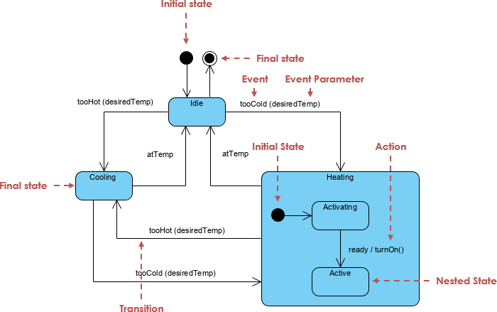
Core Elements & Notations (You Need to Know)
Here’s a breakdown of the essential building blocks of a UML State Machine Diagram. Learn these, and you’ll understand any diagram you see.
| Element | Symbol | Purpose | Example |
|---|---|---|---|
| State | Rectangle with rounded corners | Represents a condition or situation | LoggedIn, Processing, OutOfStock |
| Initial Pseudostate | Solid black circle | Start of the diagram | → from initial state |
| Final Pseudostate | Black circle inside a white circle | End of the diagram | → to final state |
| Transition | Arrow with label | Event → State change | paymentReceived → Paid |
| Event | Text on arrow | What triggers the change | paymentReceived |
| Guard | [condition] in brackets |
Only trigger if condition is true | [stockAvailable] |
| Action | action after → |
What happens during transition | sendConfirmation() |
| Entry/Exit Action | entry: action or exit: action |
Runs when entering/exiting a state | entry: logLogin() |
| Composite State | Nested states inside a larger state | Sub-states within a parent | Processing → Shipping, Billing |
| Orthogonal Region | Multiple parallel regions | Concurrent behaviors | Payment and Shipping running at once |
| History Pseudostate | H or Hs/Hd |
Return to last substate | shallow history (Hs) on Cancelled |
📌 Pro Tip: Always label transitions with event [guard] → action.
Example:paymentReceived [stockAvailable] → sendConfirmation()
Real-World Example: E-Commerce Order Lifecycle
Let’s walk through a real beginner-friendly example.
🛒 Scenario: An Order in an E-Commerce System
We want to model the lifecycle of an order from creation to delivery.
✅ States:
CreatedPending PaymentPaidProcessingShippedDeliveredCancelledRefunded
🔄 Transitions:
| Event | From | To | Guard | Action |
|---|---|---|---|---|
paymentReceived |
Pending Payment |
Paid |
— | sendConfirmation() |
cancelOrder |
Any | Cancelled |
— | notifyCustomer() |
shipOrder |
Processing |
Shipped |
[stockAvailable] |
updateTracking() |
deliveryConfirmed |
Shipped |
Delivered |
— | updateStatus() |
paymentFailed |
Pending Payment |
Cancelled |
[paymentInvalid] |
logFailure() |
🧩 Composite & Orthogonal States:
Processingis a composite state with sub-states:Billing,Packing,ShippingPaymentandShippingcan run in parallel → use orthogonal regions
🎨 Visual Layout (Simplified):
[Initial] → Created
             ↓
     [Pending Payment]
             ↓
     [Paid] → [Processing] → [Shipped] → [Delivered]
             ↓           ↘
     [Cancelled]   [Billing] → [Packing] → [Shipping]
             ↓
     [Refunded]
PlantUML State Diagram Code
@startuml

[*] --> Created

Created --> PendingPayment : submit

PendingPayment --> Paid : payment OK
PendingPayment --> Cancelled : cancel / fail

Paid --> Processing : start processing

Processing --> Shipped : packed & handed over
Processing --> Cancelled : cancel before shipping

Shipped --> Delivered : delivered

Cancelled --> Refunded : refund issued

Delivered --> [*]

@endumlUML State Diagram
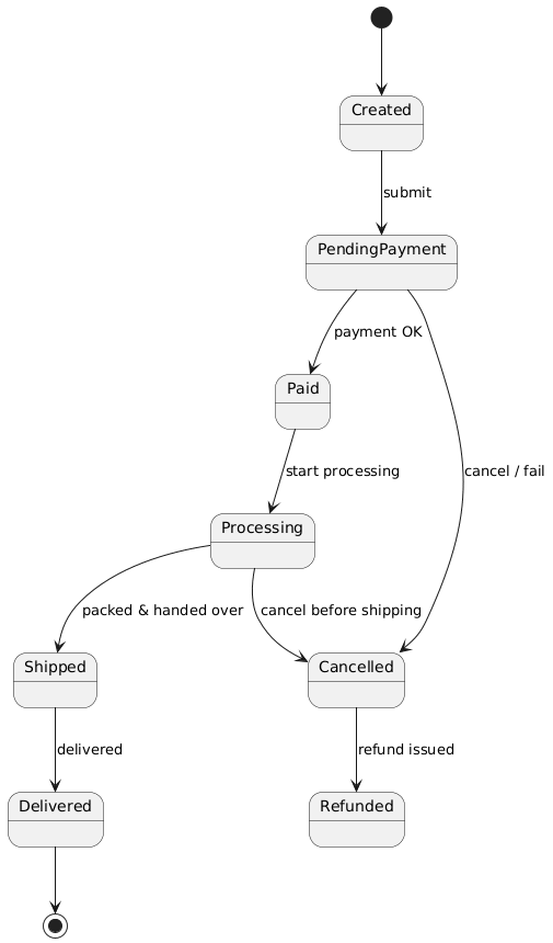
🧠 Note: The AI tool will auto-layout this for you — no need to worry about messy arrows!
How to Create a State Machine Diagram (Step-by-Step for Beginners)
Step 1: Identify the System & Its States
Ask:
“What are the main conditions the system can be in?”
👉 Example: For a user login, states are: Logged Out, Logging In, Logged In, Locked Out.
Step 2: List the Events That Trigger Changes
“What causes the system to change state?”
👉 Example: clickLogin, invalidPassword, timeout, logout
Step 3: Define Transitions with Events, Guards & Actions
“When does the system move from one state to another?”
👉 Example:
clickLogin → Logged In
invalidPassword [attempts > 3] → Locked Out
Step 4: Add Entry/Exit Actions (Optional but Helpful)
“What should happen when entering or leaving a state?”
👉 Example:
entry: logLoginAttempt() on Logging In
exit: clearSession() on Logged Out
Step 5: Use Composite States & Orthogonal Regions (For Advanced Cases)
“Can multiple behaviors happen at once?”
👉 Example: A smart thermostat can be both Heating and AutoMode at the same time → use orthogonal regions.
Why Use Visual Paradigm’s AI State Machine Diagram Generator? (Beginner-Friendly)
You don’t have to draw this by hand — Visual Paradigm’s AI State Machine Diagram Generator (2026) does it for you — fast, accurately, and with UML 2.5 compliance.
")
🔥 How It Works (For Beginners):
- Go to chat.visual-paradigm.com or open Visual Paradigm Desktop/Online
- Click AI > State Machine Diagram Generator
- Type a natural language prompt like:
“Generate a State Machine Diagram for a user login system with states: Logged Out, Logging In, Logged In, Locked Out. Events: clickLogin, invalidPassword, timeout, logout. Add guard: [attempts < 3] on login failure. Add entry action: logLoginAttempt() on Logging In.”
- Click Generate
✅ Boom! You get a fully editable, professional UML diagram in seconds — with:
- Initial and final states
- Correct transition syntax (
event [guard] → action) - Entry/exit actions
- Auto-layout (no overlapping arrows!)
- Support for composite states and history
💡 No coding. No UML syntax memorization. Just describe your system — and the AI does the rest.
Benefits of Using AI for State Machine Modeling (Especially for Beginners)
| Benefit | Why It Helps Beginners |
|---|---|
| No More Guesswork | AI understands UML 2.5 — no more invalid pseudostates or missing guards |
| Fast Prototyping | Generate a full diagram in under 1 minute |
| Error Detection | AI flags unreachable states, missing transitions, or redundant guards |
| Learning by Doing | You can see how real models look — then tweak them |
| Code Generation | Export to Java, Python, C++ — see how your model becomes real code |
| Collaboration | Share diagrams with teammates via cloud or Git |
| Iterative Refinement | Ask: “Add a ‘Reset’ button that returns to Logged Out” — and it updates instantly |
🎯 Best of all: You can ask the AI to explain anything — like “What is a history pseudostate?” — and get a beginner-friendly answer.
Beginner-Friendly Tips & Best Practices
- Start Simple
Begin with just 3–5 states. Add complexity later. - Use Domain Language
Instead of “State A → B”, say:“For a user login system, model the flow from Logged Out to Logged In with a 3-attempt lockout.”
- Use the AI Chatbot for Brainstorming
Ask:“Help me model a vending machine with coin insert, selection, and refund.”
→ The AI will generate a full diagram. - Validate Your Model
After generation, ask:“Check for unreachable states or missing guards.”
- Link to Other Diagrams
After generating a state machine, link it to your Class Diagram (e.g.,Order→State Machine) for traceability. - Export to Code
Use Tools > Generate Code to turn your diagram into real implementation.
Resources to Help You Learn (All Free & Embedded)
Here are the best beginner-friendly resources — all with direct links:
- 📘 What is a State Machine Diagram? A Comprehensive UML Guide
→ Clear explanation of purpose, components, and real-world use. - 📘 State Diagram Quick Tutorial: Master UML State Machines in Minutes
→ Beginner-friendly walkthrough with visuals. - 📘 Interactive State Machine Diagram Tool
→ Create and edit diagrams in real time using AI. - 📘 UML State Machine Diagram Tutorial and Syntax Guide
→ Learn notation, composite states, and history. - 📘 Mastering State Diagrams with Visual Paradigm AI: A Guide for Automated Toll Systems
→ Real-world case study — great for inspiration. - 📘 Generating Source Code from State Machines in Visual Paradigm
→ Turn your diagram into Java, Python, or C++ code.
Final Thoughts: You’re Ready to Start
You don’t need to be a UML expert to create powerful state machine diagrams.
With Visual Paradigm’s AI State Machine Diagram Generator, you can:
- Describe your system in plain English
- Get a professional, standards-compliant diagram in seconds
- Learn by doing — not by memorizing
🚀 Your next step?
Go to chat.visual-paradigm.com → type:
“Generate a State Machine for a user login system with login, lockout, and logout.”
→ Watch the AI build it for you.
You’ve Got This!
You now know:
- What a state machine is
- How to read and create one
- How to use AI to make it easy
- Where to learn more
🎉 Congratulations! You’ve just leveled up your system design skills.
Start small. Use the AI. Iterate. Build with confidence.
🌐 Your journey starts here: chat.visual-paradigm.com
✅ This guide is designed for beginners. All examples, links, and tools are up-to-date for 2026. No jargon. No fluff. Just clear, practical knowledge.