


In the rapidly evolving landscape of software engineering and system design, the ability to visualize complex object behaviors is paramount. Visual Paradigm has introduced a transformative approach to this challenge by integrating generative AI into its modeling platform. This comprehensive guide details how to utilize the Visual Paradigm AI platform to create, refine, and implement UML state machine diagrams through natural language processing and intelligent automation.
Understanding AI-Enhanced State Diagramming
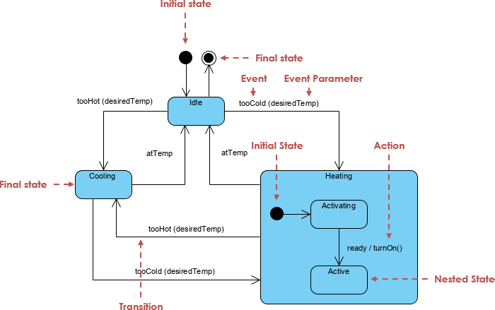
Visual Paradigm offers a unified ecosystem that merges traditional visual modeling with the power of generative AI. This integration allows system architects and developers to transform unstructured problem descriptions into structured, rigorous behavioral models effortlessly. Unlike static drawing tools, the AI-enhanced state machine features are specifically engineered to visualize object behavior and model the intricate transitions a system undergoes in response to internal or external events.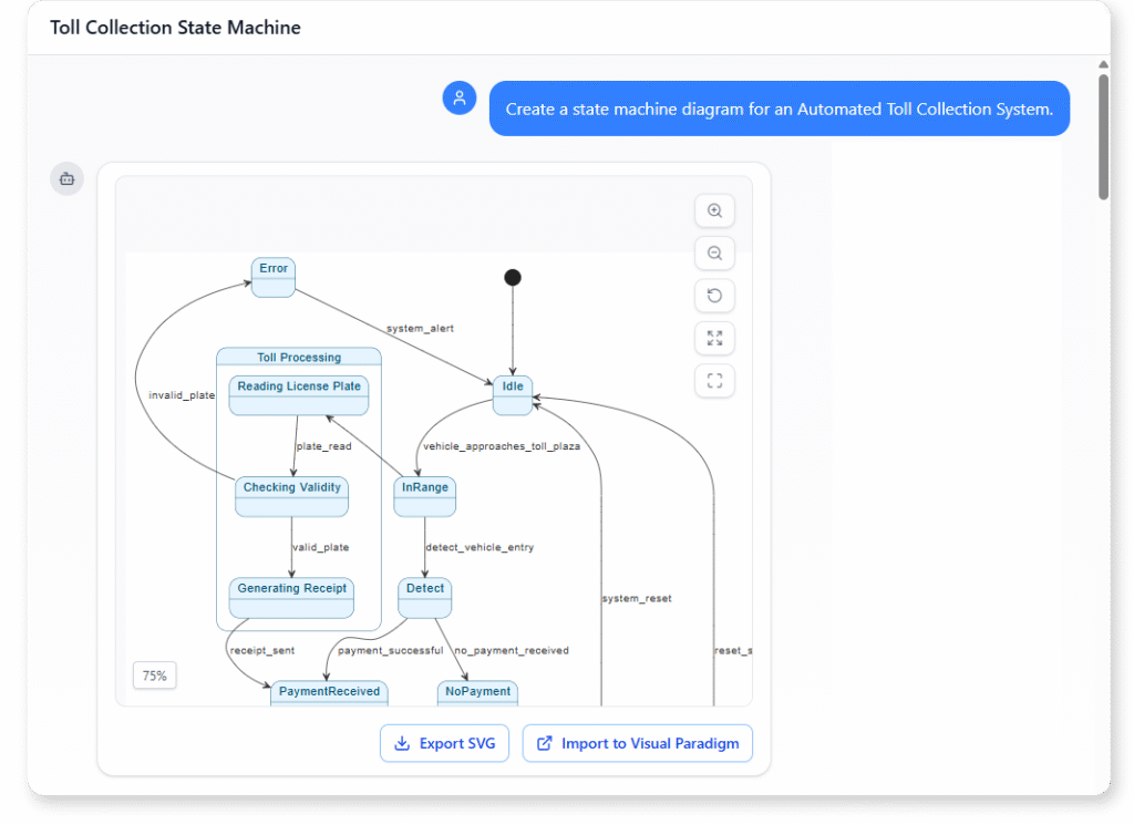
Core AI Features for Efficient Modeling
The platform leverages several sophisticated features to streamline the diagramming process:
- AI Chatbot Assistant: The central interface for this workflow is a purpose-built AI chatbot. It possesses the capability to convert natural language input into complete, presentation-ready diagrams. This feature effectively eliminates the tedious task of manual sketching, allowing users to evolve a simple text description into a comprehensive system design.
- Interactive Design Interface: Users gain access to a web-based Interactive State Machine Diagram Tool. This environment supports real-time creation and editing of models, backed by continuous generative AI support to suggest improvements or expansions.
- Context-Aware Editing: One of the most powerful capabilities is the AI’s ability to interpret instructions within the specific context of the current model. It can update existing diagrams with precise changes while strictly preserving naming conventions, structural integrity, and visual consistency.
Step-by-Step Guide to Creating State Diagrams
Creating professional UML state machines no longer requires hours of manual drag-and-drop operations. By following this AI-driven workflow, teams can accelerate their design phase significantly:
1. Describe the System Behavior
The process begins by entering a natural language description of the system’s logic into the AI Chatbot or AI Toolbox. Users should aim to articulate the scenario clearly. For example, one might describe the operational states of a 3D printer, detailing how it warms up, prints, and cools down, or outline the logic of an automated toll system.
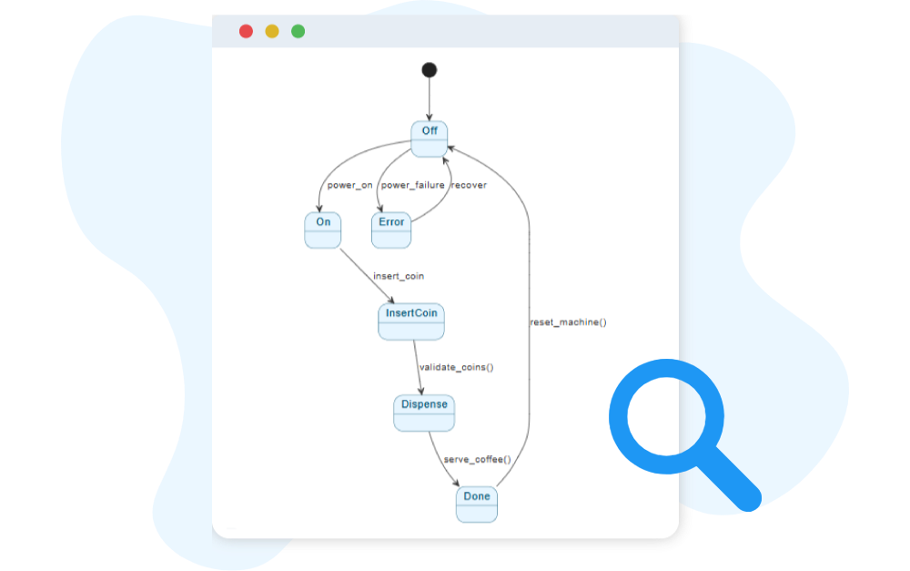
2. Instant Model Generation
Upon receiving the prompt, the AI processes the logic and instantly generates a diagram. This initial output features the necessary states and transitions derived from the text, laying a solid foundation for further refinement.
3. Define Activities
Once the structure is in place, users can refine the generated states by defining specific internal actions. This includes specifying Entry, Exit, and Do activities to ensure the diagram accurately reflects the behavior occurring within each state.
4. Refine Transitions
Using the interactive tools, designers can drag transitions between source and target states. It is crucial to name these transitions to reflect specific system events or triggers, ensuring the logic flow is readable and accurate.
5. Collaborative Refinement
Modern development is rarely a solitary endeavor. By leveraging the Visual Paradigm Circle platform, users can share the generated model via a simple URL. This facilitates real-time feedback and co-designing, allowing teams to iterate on the behavioral logic collectively.
Advanced Technical Capabilities
Visual Paradigm goes beyond simple visualization, offering advanced features that bridge the gap between design and implementation.
Automated Code Generation
A standout feature of the platform is its ability to generate source code directly from the state machine diagrams. Once the behavioral logic is modeled and validated, developers can automate the creation of the underlying code structure. This ensures highly efficient implementation of complex, state-driven logic while maintaining strict synchronization between the design artifacts and the final codebase.
Robustness Analysis and Continuity
Before moving to implementation, users can perform robustness analysis alongside state modeling. This helps define system boundaries and identify critical components early in the lifecycle. Furthermore, the AI service ensures modeling continuity, assisting users in maintaining a consistent design thread as they progress from high-level requirements to detailed state transitions.
Practical Application: The Automated Toll System
To illustrate the power of these tools, consider the common use case of modeling an Automated Toll System. Using AI-enhanced state diagrams, designers can automate and visualize complex system behaviors, such as:
- Detecting the presence of a vehicle.
- Calculating fees dynamically based on vehicle type.
- Managing physical gate transitions based on payment verification status.
By employing AI to draft and refine this logic, development teams ensure that all edge cases, exceptions, and state transitions are visualized and accounted for long before the first line of code is written.
The following articles and resources provide detailed information on using AI-powered tools to create, refine, and master UML state machine diagrams within the Visual Paradigm platform:
-
Mastering State Diagrams with Visual Paradigm AI: A Guide for Automated Toll Systems: This guide demonstrates how to utilize AI-enhanced state diagrams to model and automate the complex behaviors of an automated toll system.
-
AI-Powered UML Chatbot State Diagrams: This article explores the ways artificial intelligence improves the creation and interpretation of UML state diagrams specifically for the development of chatbot systems.
-
Definitive Guide to UML State Machine Diagrams with AI: This comprehensive resource provides a detailed guide on using AI-enhanced modeling tools to visualize object behavior through UML state machine diagrams.
-
Interactive State Machine Diagram Tool: This web-based platform allows teams to create and edit state machine diagrams in real time with generative AI support for faster software engineering workflows.
-
Visual Paradigm – UML State Machine Diagram Tool: This interactive online tool provides a dedicated interface for creating, editing, and exporting detailed UML state machine diagrams for modern software design.
-
AI Chatbot for Diagram and Model Generation: This AI-powered assistant enables users to generate various models, including state diagrams, through natural language interaction and simple text prompts.