Designing complex systems requires more than just drawing boxes and arrows. It demands a rigorous approach to logic verification. When building state machines, the visual representation often masks underlying flaws that only surface during execution. State diagram validation serves as the critical checkpoint between design and deployment. This process ensures that every transition, event, and guard condition functions as intended under real-world conditions.
Without thorough validation, systems risk encountering deadlocks, orphaned states, or unpredictable behavior. This guide explores the methodologies required to verify state logic integrity. We will examine how to identify structural weaknesses, test edge cases, and maintain consistency throughout the development lifecycle.
🧩 Understanding the Anatomy of a State Diagram
Before diving into validation, it is essential to understand the components being validated. A state diagram is a behavioral model that describes how a system reacts to events. It consists of several key elements that must be scrutinized during the review process.
- States: These represent the distinct modes of operation a system can occupy. Each state must have a clear definition of what the system is doing while in that mode.
- Transitions: These are the paths connecting states. They indicate how the system moves from one condition to another.
- Events: These are the triggers that cause a transition to occur. They can be user inputs, system signals, or time-based occurrences.
- Guards: These are boolean conditions that must evaluate to true before a transition can take place.
- Actions: These are the tasks executed upon entering, exiting, or during the transition of a state.
Each of these elements interacts dynamically. A change in one area often impacts the entire flow. Validation ensures that these interactions remain stable and logical.
⚠️ The Cost of Invalid Logic
Why invest time in validation? The consequences of skipping this step can be severe. In software engineering, logic errors in state machines often lead to system crashes, data corruption, or security vulnerabilities. Unlike simple calculation errors, state machine flaws are often non-deterministic, making them difficult to debug after deployment.
Consider a banking application where a transaction state moves from Processing to Completed. If the validation is weak, a network interruption might leave the system in a limbo state. The user sees no confirmation, yet funds might be deducted. This scenario highlights the need for robust validation.
Common Failure Modes
- Deadlocks: The system reaches a state where no valid transitions are possible, freezing the process.
- Invalid States: The system enters a state that was not defined or is logically impossible.
- Unreachable States: Certain states exist in the diagram but can never be reached from the initial state.
- Missing Transitions: An event occurs in a state, but no transition handles it, leading to undefined behavior.
- Circular Dependencies: States transition in a loop without a termination condition, causing infinite processing.
🔍 Validation Methodologies
Validation is not a single step but a layered process. Different techniques serve different purposes. A comprehensive strategy combines static analysis with dynamic testing.
1. Static Analysis and Walkthroughs
Static analysis involves reviewing the diagram without executing the code. This is often the first line of defense. Team members walk through the diagram sequentially to verify logical flow.
- Consistency Check: Ensure that all states have a defined start and end point.
- Completeness Check: Verify that every event in every state has a corresponding transition.
- Readability Check: Ensure the diagram is understandable to other developers and stakeholders.
This method relies on human expertise. It is effective for catching structural errors but may miss complex runtime interactions.
2. Dynamic Testing and Simulation
Dynamic testing involves simulating the state machine with various inputs. This approach validates that the logic holds up when the system is actually running.
- Path Coverage: Attempt to traverse every possible path in the diagram.
- Boundary Testing: Test transitions that occur at the limits of guard conditions.
- Stress Testing: Introduce high-frequency events to see if the state machine handles concurrency correctly.
Automation tools can assist in generating test cases based on the diagram structure. However, the test scenarios must be carefully designed to cover the business logic requirements.
3. Formal Verification
For critical systems, formal verification methods can be employed. These mathematical techniques prove that the state machine satisfies specific properties, such as safety or liveness.
- Safety Properties: Ensuring that bad states are never reached.
- Liveness Properties: Ensuring that the system eventually reaches a desired state.
While powerful, formal verification requires specialized knowledge and tools. It is often reserved for safety-critical domains like aviation or medical devices.
📊 Comparison of Validation Techniques
Understanding the strengths and weaknesses of each method helps in selecting the right approach for your project.
| Technique | Cost | Depth of Coverage | Best Used For |
|---|---|---|---|
| Manual Walkthrough | Low | Shallow | Early design phase, conceptual review |
| Dynamic Testing | Medium | Deep | Integration phase, regression testing |
| Formal Verification | High | Comprehensive | Critical safety systems, high-reliability requirements |
| Code Review | Medium | Medium | Verifying implementation matches design |
🚫 Detecting Common Structural Flaws
Specific patterns often indicate underlying issues. Recognizing these patterns during validation can save significant debugging time later.
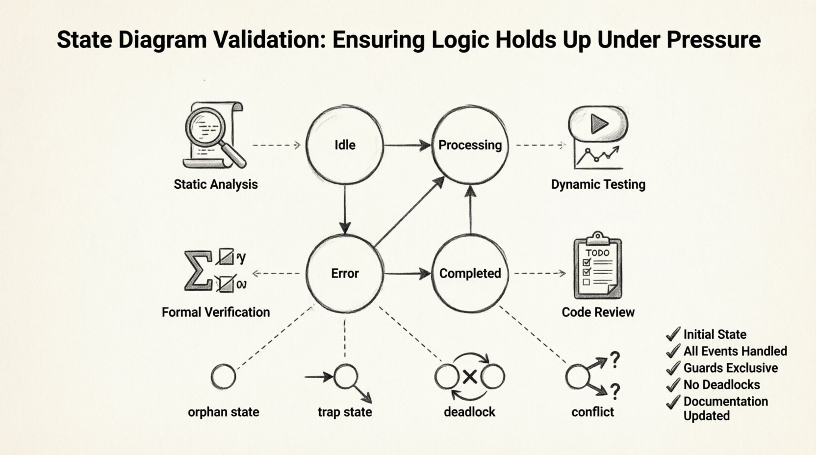
1. The Orphan State
An orphan state is a state with no incoming transitions except for the initial state. If the system cannot enter this state through normal flow, it is likely a design error.
Validation Step: Trace backwards from every state to the initial node. If a state is isolated, verify if it is intended to be unreachable or if a transition is missing.
2. The Trap State
A trap state is a state where, once entered, the system cannot leave. This is often caused by missing outgoing transitions.
Validation Step: Check every state for outgoing edges. If a state has no exits, determine if it is an end state or an error.
3. The Conflict
Conflicts occur when multiple transitions are possible for the same event from the same state. This leads to non-deterministic behavior.
Validation Step: Ensure that guards are mutually exclusive. If two transitions share an event, their guard conditions must not overlap.
4. The Deadlock
A deadlock happens when the system enters a state with no valid transitions for the current event.
Validation Step: Simulate the system with every possible event in every state. If an event has no handler, a default transition or error handling mechanism is required.
🔄 Integration with Development Workflows
Validation should not be an afterthought. It must be integrated into the development workflow to be effective.
- Design-First Approach: Define the state diagram before writing code. This ensures the architecture is sound before implementation begins.
- Version Control: Treat state diagrams as code. Store them in version control systems to track changes over time.
- Peer Review: Require multiple eyes on the diagram before approval. Different perspectives catch different errors.
- Documentation: Keep the diagram synchronized with the documentation. Outdated diagrams lead to confusion and bugs.
🛠️ Maintaining Logic Integrity Over Time
Systems evolve. Requirements change. New features are added. Every change poses a risk to the existing state logic.
Impact Analysis
When modifying a state diagram, perform an impact analysis. Determine which states and transitions are affected by the change.
- Identify Dependencies: Map out how the new feature interacts with existing states.
- Check Side Effects: Ensure that the new transition does not break existing workflows.
- Update Documentation: Reflect all changes in the diagram and associated specs.
Automated Regression Checks
As the system grows, manual testing becomes inefficient. Implement automated checks that verify the state machine behavior against the diagram.
- Snapshot Testing: Capture the state of the system at specific points and compare it to expected values.
- Contract Testing: Define contracts for state transitions and enforce them in the test suite.
- Monitoring: Use runtime monitoring to detect state anomalies in production environments.
📝 Best Practices for Clear Diagrams
A clear diagram is easier to validate. Complexity hides errors. Simplicity reveals them.
- Limit Complexity: If a diagram becomes too crowded, break it down into sub-machines or hierarchical states.
- Use Naming Conventions: Name states and events consistently. Clear names reduce ambiguity.
- Group Related States: Visually group states that belong to the same functional area.
- Keep it Current: A diagram that does not match the code is worse than no diagram at all.
🧪 Creating a Validation Checklist
To ensure consistency, create a checklist for every state diagram review.
| Item | Check |
|---|---|
| Initial State Defined | Yes / No |
| Final States Defined | Yes / No |
| All Events Handled | Yes / No |
| Guards are Exclusive | Yes / No |
| No Deadlocks Present | Yes / No |
| No Orphan States | Yes / No |
| Documentation Updated | Yes / No |
Use this checklist as a mandatory part of the sign-off process. It provides a tangible record that validation was performed.
🔗 The Relationship Between Design and Code
There is often a gap between the visual diagram and the actual implementation. This gap is where most bugs hide.
Code Generation: If using code generation tools, validate the generated output against the diagram.
Code Review: When reviewing code, check if the implementation matches the state machine logic. Look for hardcoded states that bypass the diagram.
Refactoring: When refactoring code, update the diagram simultaneously. Do not let the diagram drift away from the implementation.
🌟 Real-World Scenarios
Consider an e-commerce order processing system. The order moves through states like Created, Paid, Shipped, and Delivered.
If a user cancels an order while it is Shipped, the diagram must define how to handle this. Does it revert to Processing? Does it move to Cancelled? Without validation, the code might simply ignore the event, leaving the order in a stuck state.
Consider a medical device. A device might have states like Idle, Active, and Error. If an error occurs, the device must move to Error immediately. Validation ensures that this transition is prioritized and cannot be blocked by other events.
📈 Measuring Validation Success
How do you know if your validation efforts are working? Track metrics over time.
- Defect Density: Measure the number of state-related bugs per module.
- Coverage Rate: Track the percentage of states and transitions covered by tests.
- Mean Time to Recovery: Measure how quickly the system recovers from state errors in production.
- Review Cycle Time: Monitor how long it takes to validate a diagram change.
Improving these metrics indicates that the validation process is maturing.
🛠️ Tools and Automation
While no specific software is endorsed, the industry offers various tools to assist in validation.
- Diagram Editors: Use tools that enforce syntax rules for state diagrams.
- Test Frameworks: Integrate state machine testing libraries into your test suite.
- Static Analyzers: Use tools that scan the diagram for structural anomalies.
Automation reduces human error and allows for more frequent validation cycles.
🎓 Training and Knowledge Sharing
Validation is a skill. Teams need training to become proficient.
- Workshops: Conduct sessions on state machine theory and best practices.
- Templates: Create templates for common state patterns to ensure consistency.
- Case Studies: Review past bugs related to state logic to understand what went wrong.
Building a culture of quality ensures that validation is taken seriously by everyone involved.
🏁 Final Thoughts on Logic Integrity
Building reliable systems is a continuous effort. State diagram validation is a cornerstone of this effort. By applying rigorous techniques, you can ensure that your logic holds up under pressure. The investment in validation pays dividends in stability and trust.
Focus on the details. Check every transition. Test every edge case. Maintain your diagrams. These actions form the foundation of a robust system. With a disciplined approach, you can manage complexity and deliver high-quality results.