Understanding the behavior of a complex system requires more than just a list of features. It demands a clear visualization of how the system responds to events over time. This is where the State Machine Diagram becomes indispensable. A state diagram lifecycle encompasses the entire journey of defining, modeling, validating, and implementing system behaviors. This process ensures that the logic governing your application remains consistent from the initial concept to the final production environment.
This guide explores the detailed stages of the state diagram lifecycle. We will examine how to capture requirements, translate them into visual models, validate logic, and ensure the final implementation aligns with the design. By following a structured approach, teams can reduce ambiguity, prevent logic errors, and create systems that are easier to maintain.
Phase 1: Requirement Gathering and Analysis 📝
The foundation of any robust state model lies in the quality of the requirements gathered at the outset. This phase is not merely about listing features; it is about understanding the behavioral constraints of the system. Every state machine represents a specific aspect of the system’s functionality, often focusing on objects or processes that have distinct modes of operation.
Identifying the Subject of the Diagram
Before drawing a single transition, you must define the scope. A system rarely has a single state diagram. Instead, it has multiple diagrams representing different entities or processes. To determine what needs modeling, consider the following:
- Identify the Object: Is this a user session? A payment transaction? A network connection? The subject of the diagram determines the boundaries of the states.
- Determine the Lifecycle: Does the object have a clear beginning and end? State diagrams are most effective for entities with a distinct lifecycle.
- Define the Context: What external events trigger changes? Understanding the environment helps identify the triggers.
Capturing Behavioral Requirements
Once the subject is identified, the focus shifts to behavior. Stakeholders often describe systems in terms of actions, but the underlying logic is often state-based. During this phase, gather the following information:
- Initial States: Where does the process begin? Every state machine must have a defined starting point.
- Terminal States: How does the process end? Is it a successful completion, a cancellation, or an error termination?
- Triggers: What causes the system to move from one state to another? These could be user inputs, timer expirations, or external signals.
- Actions: What happens while in a state? Some states require continuous processes, while others are purely passive waiting periods.
- Guard Conditions: Are there specific conditions that must be met before a transition can occur? For example, a transition from “Pending” to “Active” might require a valid credit card.
Documenting these elements ensures that the subsequent modeling phase has a clear blueprint. Avoid vague descriptions like “the system handles the request.” Instead, specify “the system enters the Processing state upon receiving the request, provided the input is valid.”
Phase 2: Modeling and Design 🎨
With requirements in hand, the next step is translating text into a visual representation. This phase involves creating the State Machine Diagram itself. The goal is to create a model that is both accurate and readable. A diagram that is too complex becomes unreadable; one that is too simple may miss critical edge cases.
Defining States and Transitions
States represent the conditions under which an object satisfies a condition or performs an activity. Transitions represent the movement from one state to another. When designing the model, adhere to these principles:
- Keep States Atomic: A state should represent a single concept. Avoid combining multiple unrelated conditions in one box.
- Minimize Cross-Links: Try to organize transitions logically. Excessive crossing lines make the diagram difficult to trace.
- Use Hierarchical States: For complex systems, use nested states. This allows you to group related behaviors without cluttering the main diagram.
- Label Transitions Clearly: Every arrow should have a label indicating the trigger. If an action is performed during the transition, label it as well.
Handling Complexity
Real-world systems are rarely linear. They branch, loop, and merge. To handle this complexity without creating chaos, utilize specific modeling techniques:
- History States: When re-entering a composite state, did the system return to the initial sub-state or the last active sub-state? History states allow you to preserve this context.
- Entry and Exit Actions: Define what happens immediately upon entering or leaving a state. This keeps the logic localized to the state definition.
- Event Handling: Ensure that events are handled consistently. If an event occurs while in a state, does it trigger a transition, or is it ignored?
Artifact Creation
During this phase, the primary artifact is the diagram itself. However, supporting documentation is equally important. Create a legend that explains the symbols used, especially if you are using non-standard notations. Maintain a glossary of terms to ensure all team members interpret the states and transitions identically.
| Component | Description | Example |
|---|---|---|
| State | A condition or situation during the lifecycle | Order Pending |
| Transition | A link between two states | Payment Received |
| Trigger | The event that initiates the transition | User clicks “Confirm” |
| Guard | A boolean condition required for transition | [Funds Available] |
Phase 3: Validation and Verification ✅
A design is only as good as its validation. This phase ensures that the model accurately reflects the requirements and that no logical errors exist. It is often easier to find a missing transition in a diagram than in the code. This is the time to challenge the logic before implementation begins.
Completeness Checks
Review the diagram to ensure all possible paths are accounted for. Ask the following questions:
- Dead Ends: Are there states where the system gets stuck? Every state should have a defined exit or be a valid terminal state.
- Reachability: Can every state be reached from the initial state? If a state is unreachable, it is likely a design error.
- Completeness of Transitions: For every state and every possible event, is there a defined behavior? If an event occurs in a state and no transition is defined, the system might ignore the event or crash.
Consistency Checks
Ensure that the diagram aligns with other system models. A state diagram should not contradict the sequence diagrams or class diagrams used in the same project. Verify that:
- The data structures required to support the states exist in the domain model.
- The operations triggered by state changes match the methods defined in the architecture.
- The lifecycle of the object matches the business rules.
Peer Review Process
Conduct a formal review session. Walk through the diagram with stakeholders and developers. Use the diagram as a script for a walkthrough. Ask reviewers to simulate scenarios:
- What happens if the user cancels during the “Processing” state?
- What happens if the network fails while in the “Waiting” state?
- How does the system handle rapid-fire events?
This collaborative approach often uncovers edge cases that the primary designer might have overlooked. Document all findings and update the model accordingly.
Phase 4: Implementation Mapping 🧩
Once the design is validated, it must be translated into code. This phase involves mapping the visual elements of the state diagram to the programming constructs used in the software. While the diagram is abstract, the implementation must be concrete.
Choosing an Implementation Strategy
There are several ways to implement state logic. The choice depends on the language and architecture:
- Switch-Case Statements: Simple state machines can be implemented using conditional logic. Each state corresponds to a case, and transitions update the state variable.
- State Design Pattern: For complex systems, encapsulate each state in its own class. This allows behavior to be localized to the state object.
- State Machine Libraries: Some environments provide built-in state machine libraries that manage transitions and history automatically.
- Database State Flags: In persistent systems, the state might be stored in a database column, with triggers or application logic handling the transitions.
Mapping Logic to Code
When mapping the diagram to code, maintain a clear correspondence. Every state in the diagram should ideally have a corresponding constant or class. Every transition should map to a function or a method call. This one-to-one mapping makes debugging easier.
- State Variables: Define constants for all states. Do not use magic strings.
- Transition Functions: Create specific handlers for each transition. If a transition triggers an action, ensure the action is called within the handler.
- Guard Conditions: Implement guard conditions as boolean checks before allowing the transition.
Handling Asynchronous Events
Real-world systems often deal with asynchronous events. A state machine must handle events that arrive out of order or while the system is busy. Implement queues or buffers to manage events that cannot be processed immediately. Ensure the state machine does not crash when faced with unexpected event ordering.
Phase 5: Testing and Quality Assurance 🛡️
Testing the state machine is distinct from testing functional features. You are testing the logic flow rather than just the output. The goal is to verify that the system moves through states correctly in response to inputs.
State Coverage Testing
Aim to achieve full state coverage. Every state and every transition should be executed at least once during testing. Use the diagram as a test plan. Create test cases that specifically target:
- Normal Flow: Successful transitions from start to finish.
- Exception Flow: Transitions triggered by errors or invalid inputs.
- Boundary Conditions: Transitions that occur at the edge of valid inputs.
Regression Testing
State machines are prone to regression errors when logic changes. A change in one state might inadvertently affect another. Maintain a suite of regression tests that cover the entire lifecycle. Whenever a transition is modified, re-run the relevant test cases to ensure no side effects occurred.
Performance and Load Testing
State machines can become bottlenecks if they are too complex. High-frequency events can overwhelm the state management logic. Test the system under load to ensure it can handle the required number of transitions per second. Monitor memory usage, as state machines that retain too much context can lead to memory leaks.
| Test Type | Focus Area | Success Criteria |
|---|---|---|
| State Coverage | All states visited | 100% of states executed |
| Transition Coverage | All paths taken | 100% of transitions executed |
| Error Handling | Invalid inputs | System remains stable |
| Concurrency | Simultaneous events | No race conditions |
Phase 6: Deployment and Maintenance 🚀
The lifecycle does not end at deployment. State machines in production require monitoring and maintenance. The behavior of the system in the real world may differ from the design due to unforeseen conditions.
Logging and Tracing
Implement robust logging for state transitions. When a state changes, log the previous state, the new state, the trigger, and the timestamp. This trace is invaluable for debugging production issues. If a user reports a problem, you can trace the exact path they took through the system.
- Trace Logs: Record every transition event.
- Context Data: Log relevant data associated with the transition, such as user IDs or transaction IDs.
- Error Logs: Record any failed transitions or rejected events.
Versioning and Updates
State machine logic may evolve. New requirements will necessitate new states or transitions. When updating the model:
- Backward Compatibility: Ensure that new states do not break existing data. Old records might need to be migrated to new states.
- Documentation: Update the diagram immediately after code changes. The diagram must always reflect the current implementation.
- Rollback Plans: Have a plan to revert to the previous state logic if a new deployment causes critical failures.
Monitoring Anomalies
Set up alerts for unexpected state transitions. If a system moves from “Completed” back to “Pending,” it indicates a logic error or a data integrity issue. Monitoring these anomalies allows you to detect problems before they impact users.
Common Pitfalls and Best Practices ⚠️
Even with a structured lifecycle, errors can occur. Being aware of common pitfalls helps in avoiding them.
Common Pitfalls
- Over-Modeling: Creating state diagrams for processes that do not have distinct states. Not every process needs a state machine.
- State Explosion: Creating too many states that make the system unmanageable. Refactor by using composite states.
- Ignoring Error States: Focusing only on the happy path. Every state machine needs robust error handling states.
- Missing Guards: Allowing transitions without necessary conditions, leading to invalid system states.
Best Practices
- Keep it Simple: Start with a high-level diagram. Add detail only when necessary.
- Use Consistent Naming: Ensure state names are consistent across all diagrams and code.
- Automate Validation: Use tools to check for unreachable states or missing transitions.
- Collaborate Early: Involve developers and testers during the design phase to ensure feasibility.
Summary of Key Considerations 📋
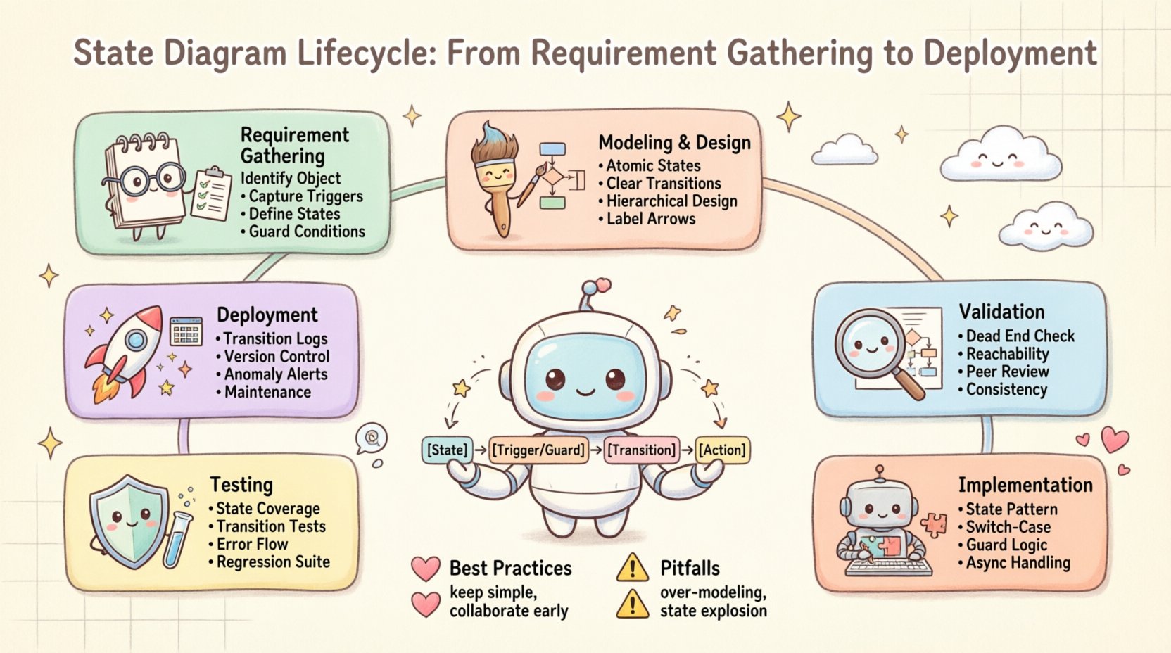
The state diagram lifecycle is a rigorous process that bridges the gap between abstract requirements and concrete code. By following these phases—Requirements, Design, Validation, Implementation, Testing, and Deployment—you ensure a high-quality system behavior model.
Key takeaways include:
- Clear requirements are the bedrock of accurate modeling.
- Visual validation catches logic errors before coding begins.
- Implementation must maintain a direct mapping to the design.
- Testing must cover all states and transitions, not just features.
- Production monitoring is essential for long-term maintenance.
Adhering to this lifecycle reduces technical debt and improves system reliability. It provides a shared language for stakeholders and developers, ensuring everyone understands how the system behaves under various conditions.