Designing a robust system requires more than just connecting components visually; it demands rigorous logical verification. When constructing a Data Flow Diagram, the visual representation of information movement is only as good as the logic driving it. Errors in this design phase can cascade into significant operational failures later. This guide provides a deep dive into identifying and rectifying logic errors within flow designs to ensure data integrity and process reliability. 🧠
Understanding the Foundation of Flow Design 🏗️
Before identifying errors, one must understand the architecture of a standard Data Flow Diagram. These diagrams map the movement of data through a system, highlighting external entities, processes, data stores, and the flows connecting them. The primary purpose is to visualize how information enters, transforms, and exits a system. When the logic governing these movements is flawed, the resulting system architecture becomes unstable.
Logic errors differ from syntax errors. A syntax error prevents a diagram from being drawn or validated technically. A logic error implies the diagram is drawn correctly but represents an impossible or inefficient reality. For instance, a process might be depicted as receiving input without a defined output, or data might appear out of thin air. These anomalies disrupt the logical flow of information. ⚙️
Ensuring the diagram accurately reflects the business rules and data conservation laws is paramount. Every piece of data entering a process must either be transformed, stored, or passed on. Nothing should be created or destroyed without a defined mechanism. This principle is the backbone of logical consistency in flow design.
Categories of Logic Errors to Detect 🔍
Logic errors manifest in various forms within a flow design. Recognizing these categories helps in systematic review. Below are the primary types of logical inconsistencies that frequently appear during the design phase.
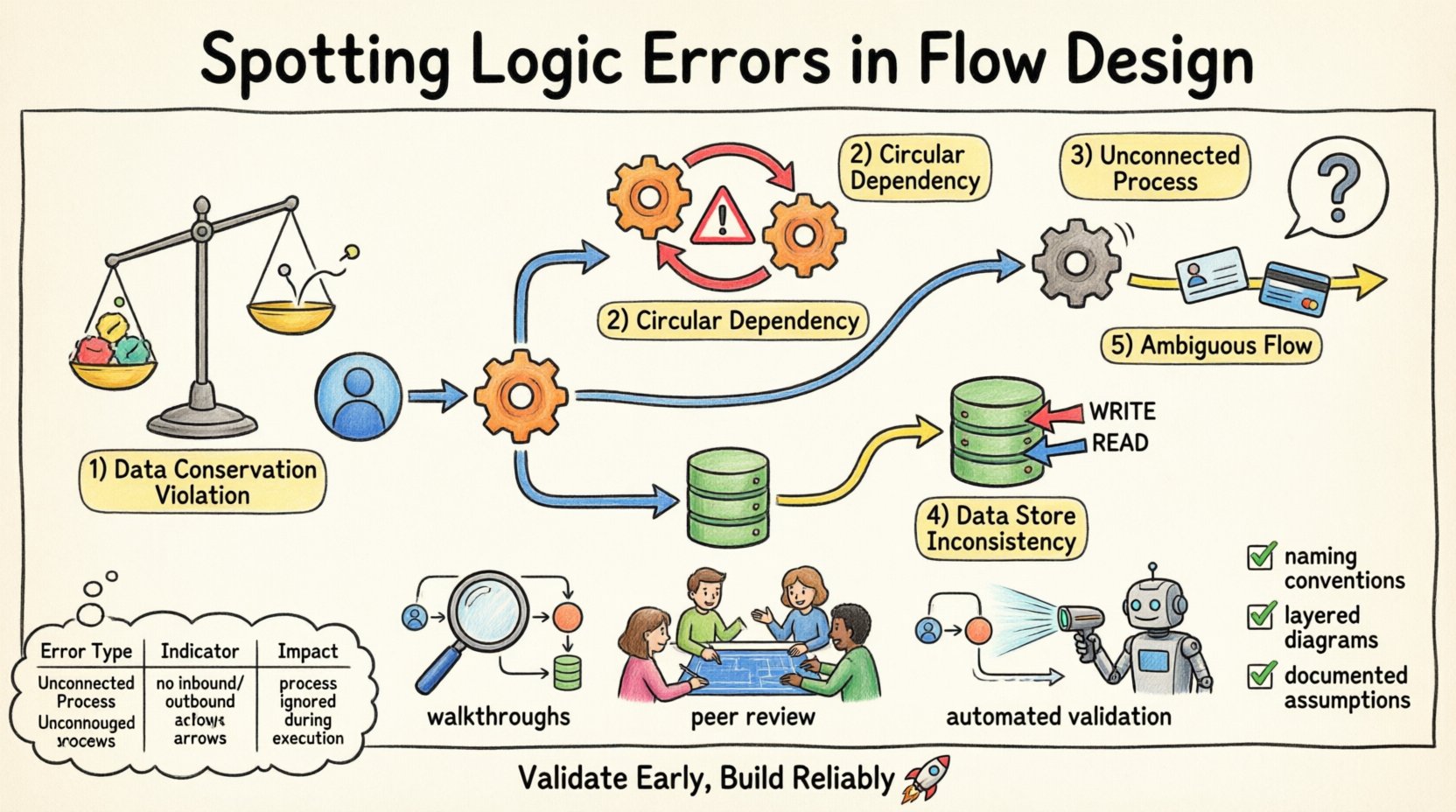
1. Data Conservation Violations 📉
The law of data conservation states that data cannot be created or destroyed within a process. If a flow diagram shows data emerging from a process without a clear source, it violates this law. Conversely, if data enters a process and disappears without being stored or output, it is lost. This often happens when a designer forgets to draw an output arrow.
For example, if a customer order process receives order details but only outputs a confirmation receipt, the payment information is missing. This indicates a gap in the logic. The system cannot function without accounting for all inputs and outputs.
2. Circular Dependencies 🔄
Circular dependencies occur when Process A feeds data to Process B, which then feeds data back to Process A without an intermediate step. In a static diagram, this looks like a loop. While loops exist in time-based systems, in a logical flow design, they often indicate a deadlock or an infinite recursion that the system cannot resolve.
Identifying these requires tracing the path of data. If a process depends on the output of another process that is itself waiting for the first process, the flow stalls. This is a critical logic error that halts system execution.
3. Unconnected Processes 🚫
An unconnected process is one that has no incoming data flows. Without input, a process cannot execute. It is a logical island. Similarly, a process with no outgoing flows does not contribute to the system’s overall output. While internal processes might exist without direct external output, they must eventually feed into a chain that reaches a data store or external entity.
Isolated processes suggest incomplete design. They consume resources but provide no value. Finding these requires a connectivity analysis of every node in the diagram.
4. Data Store Inconsistencies 🗄️
Data stores represent persistent information. Logic errors arise when processes read from or write to a data store without proper authorization or context. For instance, a process might update a record without verifying if the user has permission, or a process might read data that is only written by a different process that hasn’t run yet.
Another common issue is a data store being read and written simultaneously by different processes without synchronization. This creates race conditions in the logical model. The diagram must show clear write and read paths to avoid ambiguity.
5. Ambiguous Data Flows 🌫️
Data flows must be named and described clearly. An ambiguous flow is one that carries multiple types of data without distinction. If a single arrow represents both “User ID” and “Credit Card Number,” the logic is flawed because these data elements have different security and processing requirements.
Separating these flows ensures that each piece of information is handled according to its specific rules. Ambiguity leads to security vulnerabilities and processing errors downstream.
| Error Type |
Indicator |
Impact |
| Data Conservation |
Data appears/disappears |
Data loss or corruption |
| Circular Dependency |
Process A → Process B → Process A |
System deadlock |
| Unconnected Process |
No input or output arrows |
Resource waste |
| Data Store Inconsistency |
Uncontrolled read/write |
Data integrity issues |
| Ambiguous Flows |
Mixed data types in one flow |
Security risks |
Methodologies for Detection 🛡️
Once the types of errors are known, the next step is establishing a methodology to find them. A passive review is often insufficient. Active interrogation of the diagram is required.
Step-by-Step Walkthroughs 🚶
Conduct a mental walkthrough of the diagram. Start from an external entity and trace the data through every process to a data store or another entity. Ask questions at every node. Does this process have enough input to run? Does it produce the expected output? If I were to execute this logic, where would the data go?
This manual tracing forces the designer to visualize the data movement dynamically. It reveals gaps that static viewing misses. If the walkthrough gets stuck at a node, that is likely where the logic error lies.
Peer Review Sessions 👥
Another person looking at the diagram brings a fresh perspective. A reviewer can spot errors that the designer has become blind to due to familiarity. Encourage reviewers to challenge assumptions. Ask them to find the data flow that seems unnecessary or missing.
Structured review sessions reduce the chance of oversight. A checklist should be used during these reviews to ensure all error categories are covered.
Automated Validation Rules 🤖
While specific software is not named here, logic validation tools can scan diagrams for structural errors. These tools can flag unconnected nodes, missing data stores, or circular references. They act as a first line of defense against basic logical inconsistencies.
Using automated checks allows the team to focus on higher-level logic rather than structural syntax. It ensures the foundation is sound before adding complexity.
The Cost of Logical Neglect 💸
Why does this matter? Logic errors in the design phase are the most expensive to fix. If a logical flaw is discovered during coding, it requires rewriting modules. If found after deployment, it requires patching and potentially data migration.
Consider the scenario where a data flow is missing a validation step. This allows invalid data to enter the system. Later, reports generated from this data are inaccurate. The business makes decisions based on faulty information. The cost of cleaning this data and restoring trust is far higher than the cost of fixing the diagram initially.
Furthermore, logic errors can lead to security breaches. If a flow allows data to bypass a security check, sensitive information is exposed. This can result in compliance violations and legal consequences. Preventing these errors is not just about efficiency; it is about risk management.
Strategies for Prevention 🛡️
Prevention is better than detection. Implementing standards and practices during the creation of the flow design reduces the likelihood of errors occurring in the first place.
Standardized Naming Conventions 🏷️
Establish strict naming rules for processes, data stores, and flows. A process name should be a verb-noun pair, such as “Validate Order.” A flow name should describe the data, such as “Order Details.” This consistency makes it easier to spot anomalies. If a flow is named “Data,” it is likely too vague and should be scrutinized.
Consistent naming also aids in automated validation. Scripts can parse the names to check for compliance with logical structures.
Layered Diagramming 📑
Break down complex systems into multiple levels. Level 0 shows the high-level processes. Level 1 decomposes those processes into sub-processes. This hierarchical approach prevents the diagram from becoming cluttered. Clutter hides logic errors.
By zooming in on specific areas, the designer can focus on the logic of that specific subsystem without losing sight of the whole. Errors are easier to spot in focused views.
Documentation of Assumptions 📝
Every diagram comes with assumptions. Document them explicitly. If a process assumes data is always present, state that assumption. If a flow implies a time delay, note it. This documentation provides context for reviewers. It clarifies why certain logical choices were made.
When assumptions are documented, they can be challenged and validated against business requirements. This reduces the chance of hidden logic errors remaining in the final design.
Validation Checklist ✅
Before finalizing a flow design, run through this checklist. It covers the critical areas where logic errors typically hide.
- Input Completeness: Does every process have at least one incoming flow?
- Output Completeness: Does every process have at least one outgoing flow?
- Data Balance: Is the volume of data conserved across processes?
- No Dead Ends: Are there any processes that do not lead to a data store or external entity?
- Clear Naming: Are all flows and processes named descriptively?
- Security: Are sensitive data flows clearly marked and protected logically?
- Time Sensitivity: Are any timing dependencies clearly defined?
- Consistency: Do data stores match the data used in the processes?
Refining the Design 🎯
Once errors are found, the refinement process begins. This involves modifying the diagram to correct the logic. It is not always about removing elements; sometimes it is about adding missing connections.
For example, if a process has no output, determine where the data should go. Add the missing arrow to the appropriate data store or entity. If a circular dependency exists, introduce a buffer or a queue to break the loop. This might mean adding an intermediate step to the design.
Refinement is iterative. After making changes, re-run the walkthrough and the checklist. Ensure the new logic holds up under scrutiny. Do not assume the fix is complete until the diagram passes all validation steps.
Final Thoughts on Logical Integrity 💡
The integrity of a flow design determines the success of the system. Logic errors are subtle but destructive. They undermine the reliability of the entire architecture. By applying rigorous detection methods and prevention strategies, designers can build systems that function as intended.
Attention to detail during the design phase saves time, money, and effort downstream. A well-validated diagram is a blueprint for a stable system. Prioritizing logical consistency ensures that data moves correctly, securely, and efficiently through the organization. This approach leads to systems that are not only functional but also resilient to change. 🚀
Keep the focus on clarity and correctness. Every arrow matters. Every node counts. By adhering to these principles, the flow design becomes a trustworthy asset for the development team.