In the realm of software architecture and system design, clarity is paramount. When translating abstract requirements into concrete blueprints, two prominent methodologies often vie for attention: Data Flow Diagrams (DFD) and Unified Modeling Language (UML) models. Both serve critical functions in the development lifecycle, yet they approach system structure from fundamentally different perspectives. Understanding the nuances between these two modeling standards is essential for architects and analysts aiming to create robust, maintainable systems.
This analysis delves deep into the mechanics, applications, and structural distinctions of DFDs and UML diagrams. By examining their components, strengths, and limitations, we can determine the appropriate tool for specific design challenges without resorting to industry buzzwords or generic advice.
🔄 Understanding Data Flow Diagrams (DFD)
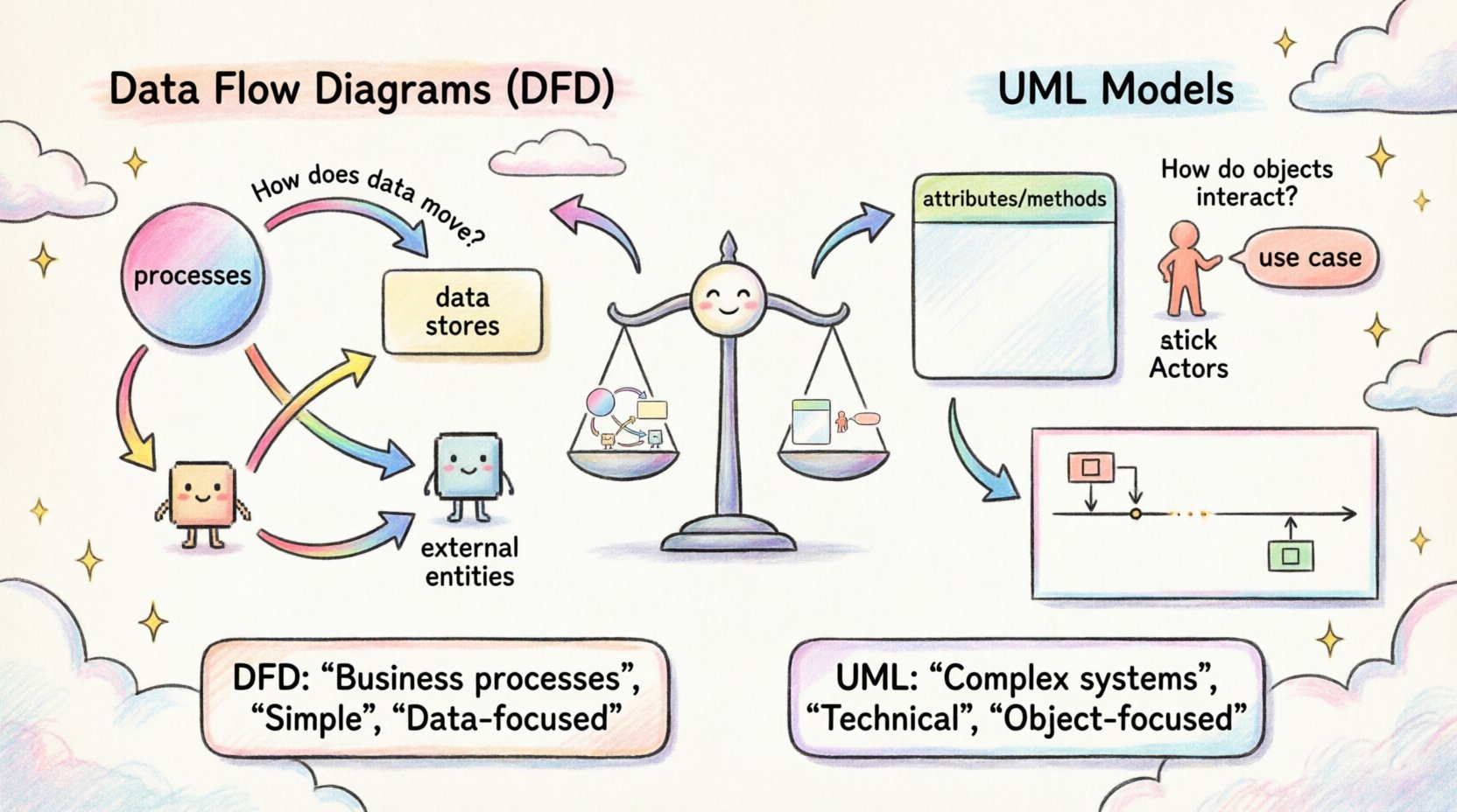
Data Flow Diagrams offer a visual representation of how information moves through a system. Originating from structured analysis techniques, DFDs focus primarily on processes and data movement rather than the objects or classes that handle that data. They answer the question: “How does data enter, change, and exit the system?”
Core Components of a DFD
A standard DFD consists of four fundamental elements, each serving a specific role in mapping system logic:
- Processes: Represented by circles or rounded rectangles, these are the actions that transform input data into output data. A process might calculate a total, validate a login, or generate a report.
- Data Stores: Shown as open-ended rectangles or parallel lines, these represent where data is saved for later retrieval. Examples include database tables, flat files, or memory buffers.
- External Entities: Depicted as squares, these are sources or destinations of data outside the system boundary. They could be human users, other software systems, or hardware devices.
- Data Flows: Arrows connecting the components, indicating the direction of data movement. Each flow must have a meaningful label describing the content being transferred.
Levels of Abstraction
DFDs are typically hierarchical to manage complexity. This allows stakeholders to view the system at varying levels of detail:
- Level 0 (Context Diagram): The highest level, showing the entire system as a single process interacting with external entities. It defines the scope.
- Level 1: Breaks the main process into major sub-processes. It shows the major data flows and stores.
- Level 2: Further decomposes specific Level 1 processes into detailed logic, often used for implementation planning.
The strength of DFDs lies in their simplicity. They do not concern themselves with how data is stored structurally or the logic of object instantiation. They are purely functional, making them ideal for understanding business workflows and transactional logic.
🏗️ Understanding UML Models
The Unified Modeling Language (UML) is a standardized modeling language used to visualize, specify, construct, and document the artifacts of a software system. Unlike DFDs, which focus on flow, UML encompasses a broader range of views, including structure, behavior, and interaction. It is deeply rooted in object-oriented design principles.
Key UML Diagram Types
UML is not a single diagram but a collection of diagram types, categorized into two main groups: Structural and Behavioral.
Structural Diagrams
- Class Diagrams: The backbone of object-oriented design. They show the system’s static structure, including classes, attributes, operations, and relationships (inheritance, association, aggregation).
- Component Diagrams: Represent the physical components of a system, such as libraries, files, and executables, and their dependencies.
- Deployment Diagrams: Illustrate the physical architecture, showing nodes (hardware) and the artifacts deployed on them.
Behavioral Diagrams
- Use Case Diagrams: Describe the interactions between actors and the system to achieve a specific goal. They focus on functionality from a user perspective.
- Sequence Diagrams: Show object interactions arranged in time sequence. They are crucial for understanding the flow of messages between objects.
- Activity Diagrams: Similar to flowcharts, these model the workflow of activities within a system. They are often used to describe complex logic within a use case.
- State Machine Diagrams: Describe the states an object can be in and the transitions triggered by events.
⚙️ Core Differences and Structural Contrasts
While both methodologies aim to document system design, their underlying philosophies differ significantly. DFDs are process-oriented, whereas UML is object-oriented. This distinction dictates how data and logic are represented.
Data vs. Object Focus
In a DFD, the primary unit of analysis is the data flow. Entities exist only to create or consume data. There is no concept of an “object” holding state or behavior. In UML, the class is the primary unit. Objects encapsulate data (attributes) and behavior (methods). This makes UML more suitable for systems where state management and object interactions are critical, such as complex enterprise applications or GUI-driven software.
Static vs. Dynamic Views
DFDs are inherently dynamic; they show movement. However, they lack a static structural view of the data itself. You cannot see the schema or the relationship between data elements in a standard DFD. UML Class Diagrams provide a static snapshot of the system’s data structure, defining the schema explicitly. This is a critical difference for database designers and backend engineers who need to understand entity relationships.
Complexity and Granularity
DFDs are generally simpler and easier to read for non-technical stakeholders. They avoid the complexity of inheritance hierarchies and polymorphism. UML diagrams, particularly Sequence and Class diagrams, can become intricate quickly. While this complexity adds detail, it can also obscure the high-level business logic if not managed carefully.
Comparison Table
| Feature |
Data Flow Diagram (DFD) |
UML Models |
| Primary Focus |
Data movement and processing |
System structure and behavior |
| Design Paradigm |
Structured Analysis |
Object-Oriented Design |
| Data Representation |
Flows and Stores |
Classes and Attributes |
| Best For |
Business processes, transaction systems |
Software architecture, complex logic |
| Stakeholder Readability |
High |
Moderate to Low (requires training) |
🧩 When to Use DFDs
Data Flow Diagrams shine in scenarios where the business process is the primary concern. They are excellent for:
- Requirements Gathering: Helping business stakeholders visualize how their data moves through the organization without getting bogged down in technical implementation details.
- Transaction Processing Systems: For systems like billing, order processing, or inventory management, where the sequence of data transformation is more important than the state of the objects.
- Legacy System Analysis: When documenting existing procedural code or batch processing systems, DFDs align well with the linear execution model.
- Security Auditing: Identifying data boundaries and ensuring sensitive information flows correctly between trust zones.
📋 When to Use UML Models
Unified Modeling Language becomes the preferred choice when the software architecture itself is the complexity driver. Use UML when:
- Building Object-Oriented Software: If the codebase relies heavily on classes, interfaces, and inheritance, UML Class and Sequence diagrams are necessary for developers to understand the code structure.
- Designing Complex Interactions: For distributed systems or microservices where message passing and timing matter, Sequence and Communication diagrams provide clarity.
- State Management: If the system relies on specific states (e.g., an order moving from “Pending” to “Shipped” to “Delivered”), State Machine diagrams are indispensable.
- Database Schema Design: Class diagrams can serve as a blueprint for relational database design, ensuring normalization and relationship integrity.
🚀 Integration and Best Practices
It is a common misconception that one must choose exclusively between DFDs and UML. In mature development environments, these tools often coexist. A project might start with a DFD to establish the business scope and then transition to UML Class Diagrams to define the technical implementation.
Maintaining Consistency
When using both, consistency is key. Ensure that the processes identified in the DFD map logically to the classes or components in the UML model. If a DFD shows a “Calculate Tax” process, the UML should reflect a “TaxCalculator” class or service that performs this action. Discrepancies between the two models can lead to implementation errors and confusion among the team.
Avoiding Over-Modeling
One pitfall in software architecture is creating diagrams that are too detailed too soon. A UML Class diagram with every single attribute and method can become unreadable. Similarly, a DFD that decomposes every minor calculation into its own process can become cluttered. Aim for the right level of abstraction for the audience. Business stakeholders need high-level flows; developers need detailed interaction logic.
Version Control for Models
Just like code, models evolve. It is important to version your diagrams. Changes in business requirements should be reflected in the DFD, which should then cascade into updates in the UML models. Maintaining a history of these changes helps in auditing and understanding the evolution of the system design.
⚠️ Common Pitfalls in Modeling
Even experienced architects can stumble when creating these diagrams. Being aware of common mistakes can save significant time during the design phase.
- Ignoring Data Stores: In DFDs, forgetting to label data stores can lead to ambiguity about where data persists. In UML, omitting relationships between classes can break the integrity of the object model.
- Mixing Metaphors: Do not try to force object-oriented concepts into a DFD. A DFD should not show inheritance or polymorphism. Keep the models pure to their respective paradigms.
- Overcomplicating the Context: A Level 0 DFD should not contain internal processes. If it does, it is not a context diagram. Similarly, a Use Case diagram should not show implementation details.
- Lack of Standardization: Ensure everyone on the team uses the same notation symbols. Deviations in symbols can lead to misinterpretation of the design intent.
🔍 Final Thoughts on Selection
The choice between Data Flow Diagrams and UML models is not about which is superior, but which is appropriate for the current phase of development and the nature of the system. DFDs provide a clear, business-centric view of information movement, making them ideal for defining scope and process. UML provides a rigorous, technical view of structure and behavior, essential for guiding complex software construction.
By leveraging the strengths of both, architects can create a comprehensive documentation strategy. Start with DFDs to align business expectations and move to UML to guide technical execution. This layered approach ensures that the final system meets functional requirements while maintaining a solid architectural foundation.
Remember that models are tools for communication, not just documentation. Their value lies in the clarity they bring to the team and the stakeholders. Whether you are mapping a simple transaction or designing a distributed cloud architecture, choosing the right notation ensures that the design intent is preserved from concept to code.