Designing a state machine diagram is a fundamental skill for anyone involved in software architecture, hardware logic, or complex process modeling. These diagrams visualize how a system behaves over time, reacting to events and changing conditions. However, despite their utility, many practitioners fall into specific traps that obscure logic and introduce bugs. This guide explores the most frequent errors found in state chart notation and provides clear, actionable strategies to correct them.
Whether you are defining the lifecycle of a user session, controlling an embedded device, or modeling a business workflow, clarity is paramount. A well-constructed diagram reduces ambiguity. A poorly constructed one creates a roadmap to failure. We will examine these pitfalls in depth, ensuring your models are robust, maintainable, and accurate.
Understanding State Machine Diagrams 📊
A state machine diagram, often referred to as a state chart or state transition diagram, represents the distinct states of an object and the transitions between them. Each state defines a specific condition or mode during the object’s lifecycle. Transitions occur when a specific event is triggered, provided any associated guard conditions are met.
Key components include:
States: Nodes representing conditions (e.g., Idle, Processing, Completed).
Transitions: Arrows connecting states, indicating movement.
Events: Triggers that initiate a transition (e.g., Button Press, Timeout).
Actions: Activities performed during a transition or within a state.
Initial/Final States: Entry and exit points for the diagram.
When these elements are misaligned, the resulting behavior of the system becomes unpredictable. Let us analyze the specific mistakes that lead to this confusion.
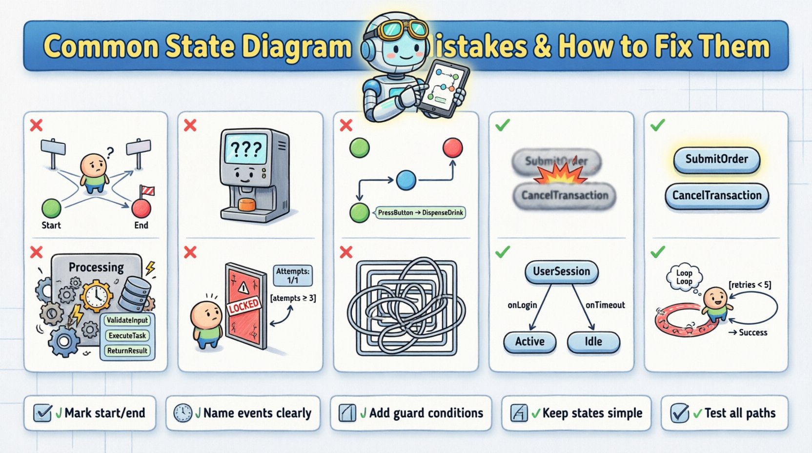
Mistake 1: Missing Initial or Final States 🚫
One of the most critical oversights is neglecting to define where the system begins and where it ends. Without a clear start point, the system may initialize in an undefined state, leading to runtime errors. Similarly, without a defined end state, the system might enter an infinite loop or fail to release resources properly.
The Problem
Beginners often draw states in a circle, connecting them without anchoring the flow. This creates ambiguity about the entry point. If a system starts in State B instead of State A, the logic governing State A‘s entry actions will never execute.
The Fix
Always explicitly mark the initial state with a solid black circle pointing to the first logical state.
Define a final state (a solid black circle within a larger circle) for termination scenarios.
Ensure every path eventually leads to a termination point or a valid idle state.
Mistake 2: Undefined or Missing Transitions 🚧
A state diagram must account for all valid events. If a state exists but has no outgoing transitions for a specific event, the system does not know how to react. This is often called an “implicit transition” or an error in logic coverage.
The Problem
Imagine a vending machine in the Ready state. If a user inserts money, it moves to Dispensing. But what if the user presses Cancel? If there is no transition defined for Cancel while in Ready, the machine ignores the input. In complex systems, this silence can be catastrophic.
The Fix
Conduct a thorough review of all possible events for every state.
Define explicit transitions for error handling or unexpected inputs.
Use a “catch-all” transition to a Error or Reset state if specific handling is not required for every edge case.
Mistake 3: Ambiguous Event Triggers ⚠️
Events must be unique and clearly named. Using generic terms like Action or Process as event names creates confusion. Furthermore, multiple events triggering the same transition without differentiation can lead to race conditions or unintended state changes.
The Problem
If Event A and Event B both trigger a move to State X, but from different states, the diagram might look cluttered. Worse, if Event A is a subset of Event B, the logic becomes fuzzy. The system designer must ensure that the trigger is distinct enough to be identified by the processor.
The Fix
Use descriptive, verb-noun combinations for events (e.g., SubmitOrder instead of Submit).
Ensure event names are consistent throughout the diagram.
Document the source of the event (user input, system timer, external API).
Mistake 4: Overcomplicating States (Cognitive Load) 🧠
State machines are meant to simplify logic, not complicate it. A common error is creating states that are too broad or too granular. If a state contains too much internal logic, it ceases to be a state and becomes a mini-program. Conversely, too many micro-states make the diagram unreadable.
The Problem
Consider a state named Processing. If this state involves database writes, user notifications, and file uploads, it is doing too much work. This violates the Single Responsibility Principle. It makes testing difficult because you cannot isolate the failure point within the state.
The Fix
Decompose complex states into sub-states or orthogonal regions.
Ensure each state represents a single, coherent condition.
Use composite states to group related behaviors without cluttering the main flow.
Mistake 5: Ignoring Guard Conditions 🛡️
Transitions should not happen unconditionally unless the system is designed that way. Guard conditions are boolean expressions that must be true for a transition to occur. Omitting them forces the system to react to events it is not ready for.
The Problem
Imagine a login system. If the transition from Invalid Password to Locked occurs without a guard condition (e.g., Attempts >= 3), the user gets locked out after one mistake. The diagram lacks the necessary constraints to enforce business rules.
The Fix
Add guard conditions in square brackets
[condition]on transition arrows.Ensure all guard conditions are testable and verifiable.
Review guards to ensure they cover edge cases (e.g., negative numbers, null values).
Mistake 6: Incorrect Use of Hierarchy 🏗️
Advanced state machines use hierarchy to manage complexity. However, beginners often misuse this feature. They might create states that are not actually hierarchical, leading to redundancy. Or they might create deep nesting that makes the diagram impossible to trace.
The Problem
Using deep nesting can hide critical transitions. If a state is nested three levels deep, a transition might fire from a parent state that you didn’t anticipate. This makes debugging extremely difficult because the state history is not immediately visible.
The Fix
Keep hierarchy shallow (maximum two or three levels).
Use hierarchy only to share common behavior (e.g., all Payment methods share a Validating sub-state).
Document the scope of transitions: do they apply to the parent or the specific child?
Mistake 7: Self-Transitions Confusion 🔄
A self-transition occurs when an event triggers a transition that returns the system to the same state. Beginners often confuse this with a loop or a deadlock. While self-transitions are valid (e.g., for logging or validation), they must be handled carefully.
The Problem
If an event triggers a self-transition but includes an action that modifies the state’s internal data, the system must ensure it does not enter an infinite loop. For example, if a state Counting increments a counter on every tick without a limit, the system hangs.
The Fix
Ensure self-transitions have guard conditions that eventually become false.
Clearly label self-transitions with the specific event causing them.
Verify that actions within self-transitions do not block subsequent processing.
Comparative Analysis: Mistake vs. Solution 📋
To consolidate the information, the following table summarizes the key errors and their corresponding fixes.
Mistake | Impact | Solution |
|---|---|---|
Missing Initial State | Undefined system start | Mark start node clearly |
Undefined Transitions | Unhandled events | Map all event inputs |
Ambiguous Events | Logic conflicts | Use unique naming |
Over-complicated States | High cognitive load | Decompose into sub-states |
Missing Guard Conditions | Invalid state changes | Add boolean checks |
Deep Hierarchy | Hard to debug | Limit nesting levels |
Advanced Considerations: Concurrency ⚡
Some systems require multiple state machines to run simultaneously. This is known as concurrency or orthogonal regions. Beginners often try to force concurrent behavior into a single flat state diagram, resulting in a tangled web of lines.
The Problem
Attempting to model a system that has both Power Management and Network Connection in one linear flow creates unnecessary complexity. The state of the power does not necessarily dictate the state of the network.
The Fix
Use orthogonal regions to represent independent state machines within the same context.
Draw these regions side-by-side or stacked to indicate parallel execution.
Ensure transitions in one region do not inadvertently affect the other unless explicitly defined.
Documentation and Naming Conventions 📝
The visual diagram is useless if the accompanying text is vague. Naming conventions are not just about aesthetics; they are about communication between developers, stakeholders, and testers.
State Names: Use nouns or noun phrases (e.g., Order Confirmed rather than Confirming).
Event Names: Use verbs or verb phrases (e.g., Order Placed).
Action Names: Describe the effect (e.g., Send Email).
Consistency in naming allows for automated code generation and easier maintenance. If the diagram says Start but the code says Initiate, the link between design and implementation breaks.
Testing Your State Diagram 🧪
Once the diagram is drawn, it must be validated. This process is often overlooked but is essential for quality assurance.
Steps for Validation
Walkthroughs: Trace every possible path from start to finish.
Edge Case Analysis: What happens if an event occurs out of order?
Code Review: Does the implementation match the diagram exactly?
Peer Review: Have a colleague review the diagram for clarity.
Common Pitfalls in Implementation 🛠️
Even with a perfect diagram, implementation errors occur. The state machine logic in code often drifts from the design.
Hardcoded States: Avoid using magic numbers for states. Use enumerated types.
Event Bubbling: Ensure events are handled at the correct level of hierarchy.
State Persistence: If the system restarts, does it remember its state? Ensure the diagram accounts for persistence mechanisms.
Final Thoughts on State Design 💡
Creating a state machine diagram is an exercise in precision. It requires thinking through every possibility and ensuring the logic holds up under stress. By avoiding the common mistakes outlined above, you ensure that your models are not just theoretical exercises but practical tools for building reliable systems.
Remember that state diagrams are living documents. As requirements change, the diagram must evolve. Regular reviews and updates keep the model relevant. Focus on clarity, consistency, and completeness. This approach leads to systems that are easier to debug, maintain, and scale.
Start with a simple model and add complexity only when necessary. Resist the urge to over-engineer the initial design. A robust foundation is better than a complex, fragile structure. With these guidelines, you can navigate the complexities of state machine design with confidence.